
Fast Tool Changing System by Means of Synchronizing Displacement and Linkage of Main Spindle and Tool Magazine

Inactive Publication Date: 2013-12-26
LIU YI JUN
View PDF6 Cites 19 Cited by
  • Summary
  • Abstract
  • Description
  • Claims
  • Application Information

AI Technical Summary

Benefits of technology

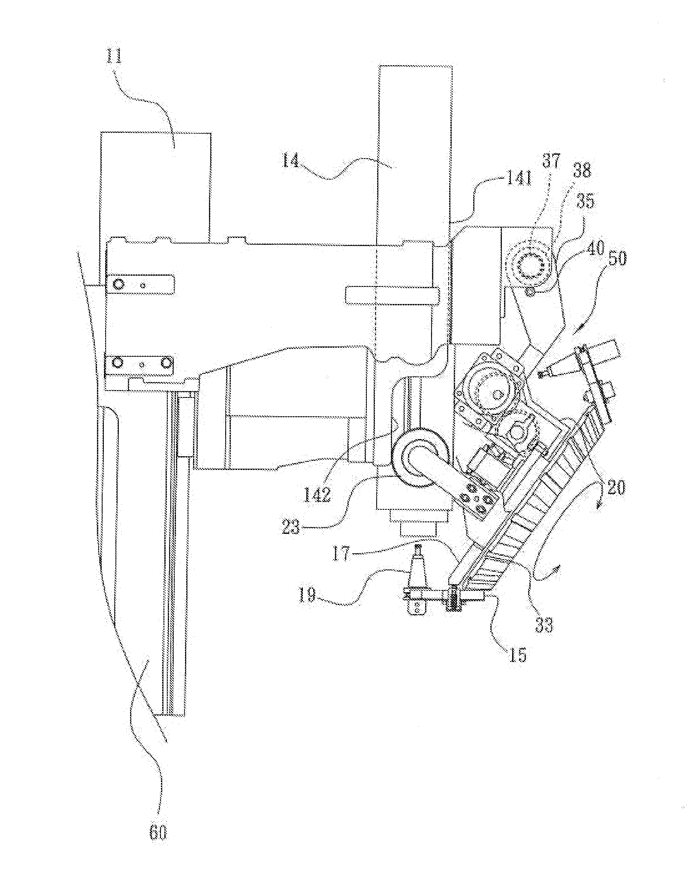
The invention provides a fast tool changing system by synchronizing displacement and linkage of a main spindle and a tool magazine. The system includes a machine body, a servo-motor, linkage panels, a roller wheel, single rod bearings, a swing arm, a tool magazine casing body, a tool tray, a positioning signal block, a stage switch, and a tool locking base. The roller wheel adjusting base is pivotally connected to the tool magazine casing body, which causes the tool magazine casing body to move smoothly when rotated. The system is designed to prevent vibration and ensure secure tool changing.

Problems solved by technology

The costs are low but, the tool changing speed is not competitive and the economical efficiency is relatively low.
The tool tray does not have a locking device for clamping the cutting tool in position, so that the tools may drop down.
The components of such a system are too many, and the structure is relatively complicated so that when the main spindle-tool magazine system and the mechanical hand are changing the tools, dropping down and / or flying away of the tools may take place.
While this is not safe, the after-service and maintenance is inconvenient, and the costs are relatively high.

Method used


Image

  • Fast Tool Changing System by Means of Synchronizing Displacement and Linkage of Main Spindle and Tool Magazine
  • Fast Tool Changing System by Means of Synchronizing Displacement and Linkage of Main Spindle and Tool Magazine
  • Fast Tool Changing System by Means of Synchronizing Displacement and Linkage of Main Spindle and Tool Magazine

Examples


Embodiment Construction

[0023]The following description is disclosed to enable any person skilled in the art to make and use the present invention. Preferable embodiments are provided in the following description only as examples and modifications will be apparent to those skilled in the art. The general principles defined in the following description would be applied to other embodiments, alternatives, modifications, equivalents, and applications without departing from the spirit and scope of the present invention.

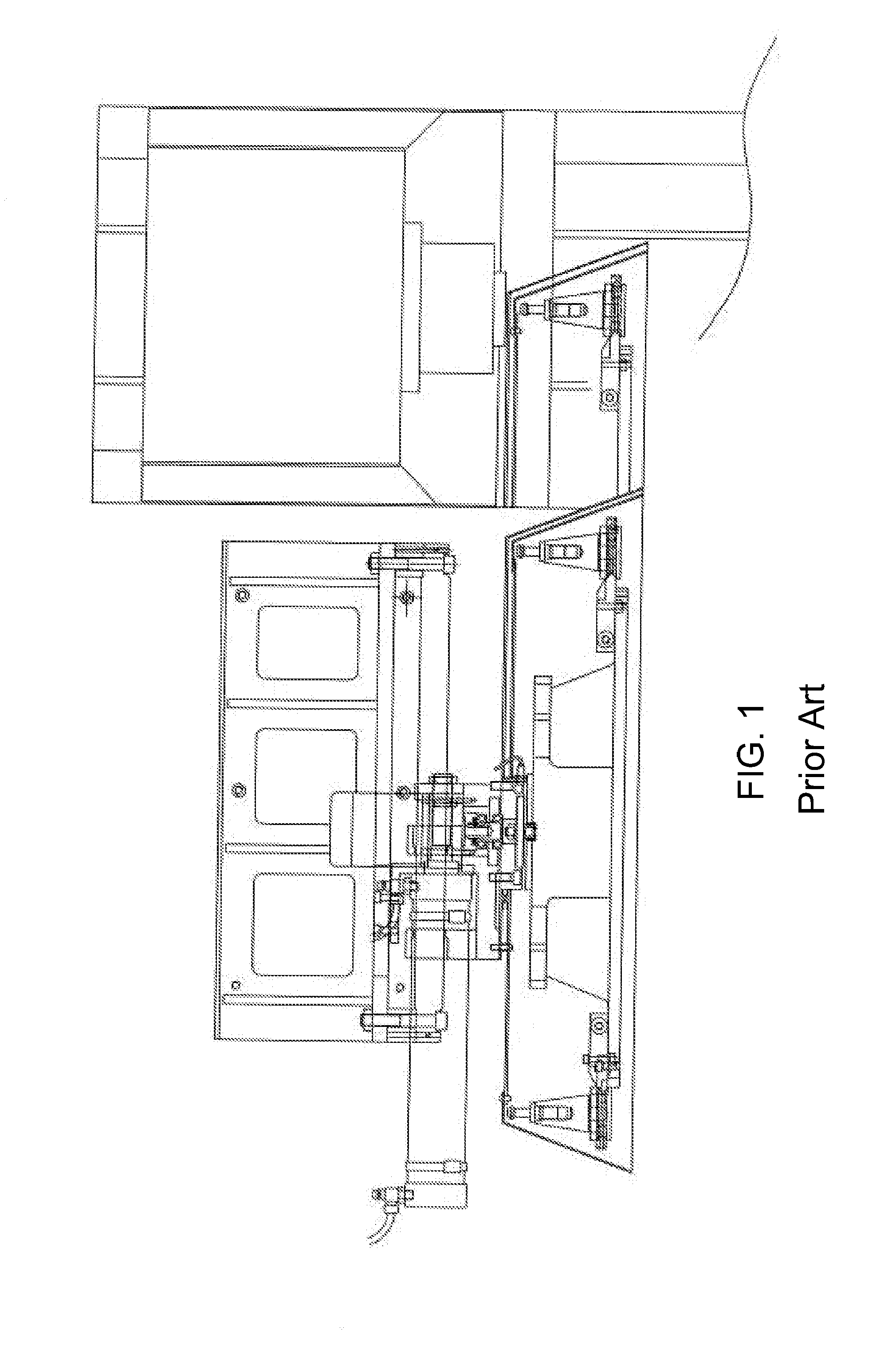
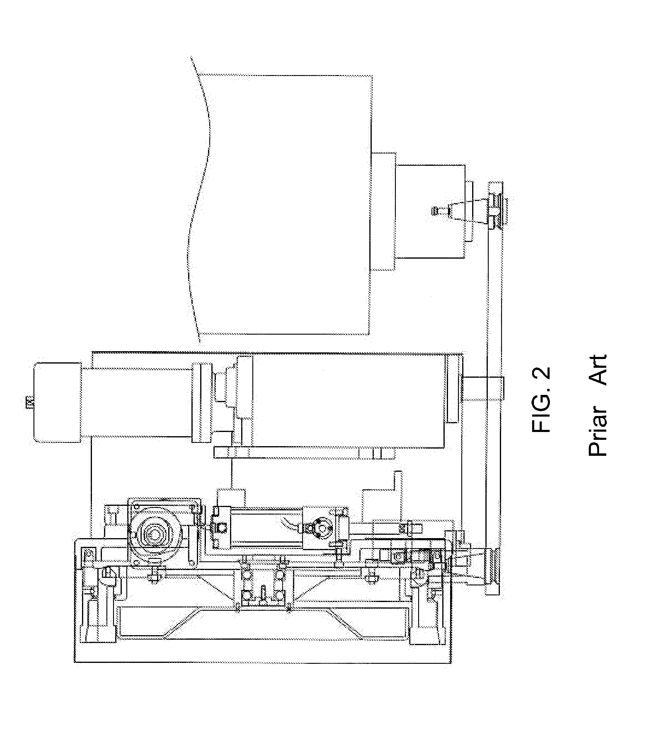
[0024]Referring to FIG. 1 to FIG. 11 of the drawings, a fast tool changing system by means of synchronizing displacement and linkage of a main spindle and a tool magazine, wherein the system comprises a machine body 60, a servo-motor 11 provided thereon for driving the main spindle 13 to raise or drop, two linkage panels 14 provided at two lateral sides of the man spindle 13 respectively which can simultaneously move with the main spindle 13 wherein each of the linkage panels 14 comprises a flat...


PUM


Abstract

A fast tool changing system by means of synchronizing displacement and linkage of a main spindle is provided, wherein when a servo-motor drives the main spindle to raise or drop, two linkage panes, which are provided at two lateral sides of the main spindle respectively and each of which comprises a flat portion and a concave portion defining a height difference, can synchronizing move. The roller wheel, which is provided on a roller wheel adjusting base at a lateral side of the cool magazine, slides on the linkage panel. Because of the heath difference, the swing arm is driven to swing, so that action of fast tool changing by means of synchronizing displacement and linkage of the main spindle can be achieved.

Description

NOTICE OF COPYRIGHT[0001]A portion of the disclosure of this patent document contains material which is subject to copyright protection. The copyright owner has no objection to any reproduction by anyone of the patent disclosure, as it appears in the United States Patent and Trademark Office patent files or records, but otherwise reserves all copyright rights whatsoever.BACKGROUND OF THE PRESENT INVENTION[0002]1. Field of Invention[0003]The present invention relates to a fast tool changing system via synchronizing linkage of a tool magazine, wherein a roller wheel, which is provided on a roller wheel adjusting base at a lateral side of the tool magazine, slides between a flat portion and a concave portion of a linkage panel, so as to achieve the fast tool changing performance via synchronizing linkage of the tool magazine. A swing arm, which is pivotally connected to the tool magazine frame, has a groove provided in a front end portion thereof for receiving an enhanced pre-pressed t...

Claims


Application Information

Patent Timeline
IPC IPC(8): B23Q3/157
CPCB23Q3/15706B23Q3/15534B23Q3/15722Y10T483/1752
Inventor LIU, YI-JUN
Owner LIU YI JUN
Learn More