Reusable in-vivo device, system and method of assembly thereof

a technology of in-vivo devices and reusable devices, which is applied in the field of reusable in-vivo devices and systems, and methods of assembling reusable in-vivo devices, can solve the problems that in-vivo devices that may be externally controlled with regard to their in-vivo location and with regard to operations that the device may perform while in-vivo might be quite expensive, and in-vivo devices, even those without maneuverability, might also be expensive to the end-user, so a a a a a a a a a a a a a a a a a a a a a a a a a a a a a a a a a a a a a a a a a a a a a a reusable in-vivo devices and in-vivo, a technology, applied in the field a reusable devices a reusable devices a reusable devices reusable devices reusable devices reusable devices reusable devices reusable devices reusable in-vivo devices reusable reusable reusable reusable devices reusable reusable reusable reusable reusable reusable reusable reusable reusable reusable reusable reusable reusable reusabl

Inactive Publication Date: 2013-12-26
GIVEN IMAGING LTD
View PDF17 Cites 10 Cited by
  • Summary
  • Abstract
  • Description
  • Claims
  • Application Information

AI Technical Summary

Benefits of technology

[0005]The present invention provides reusable in-vivo devices and systems and methods for assembling such reusable in-vivo devices, which may assist in lowering the price of these devices to the end-user. These devices should be substantially easily retrievable from within the patient, such that they could be reused for an additional operation, thereby maintaining a relatively low price.

Problems solved by technology

An in-vivo device that may be externally controlled with regard to its in-vivo location and with regard to operations that the device may perform while in-vivo might be quite expensive.
Furthermore, in-vivo devices, even those without maneuvering capabilities, e.g., autonomous capsule endoscopes, might also be expensive to the end-user.

Method used


Image

  • Reusable in-vivo device, system and method of assembly thereof
  • Reusable in-vivo device, system and method of assembly thereof
  • Reusable in-vivo device, system and method of assembly thereof

Examples


Embodiment Construction

[0031]In the following detailed description, numerous specific details are set forth in order to provide a thorough understanding of the invention. However, it will be understood by those skilled in the art that the present invention may be practiced without these specific details. In other instances, well-known methods, procedures, and components have not been described in detail so as not to obscure the present invention.

[0032]The reusable in-vivo devices, systems, and methods for assembling such reusable devices as described below provide examples of devices that are easy to assemble and reassemble following a substantially easy retrieval from within a patient's body. These devices may include various operational tools for performing all sorts of in-vivo operations once these devices reach a location of interest.

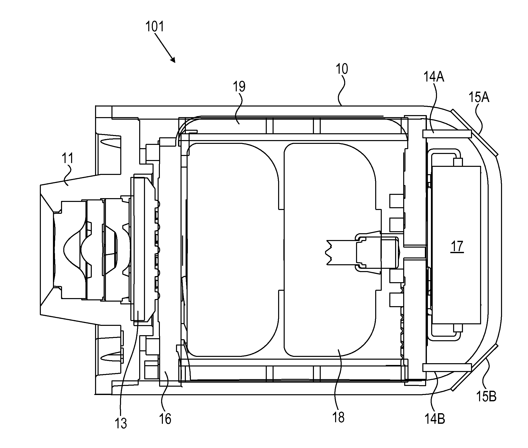
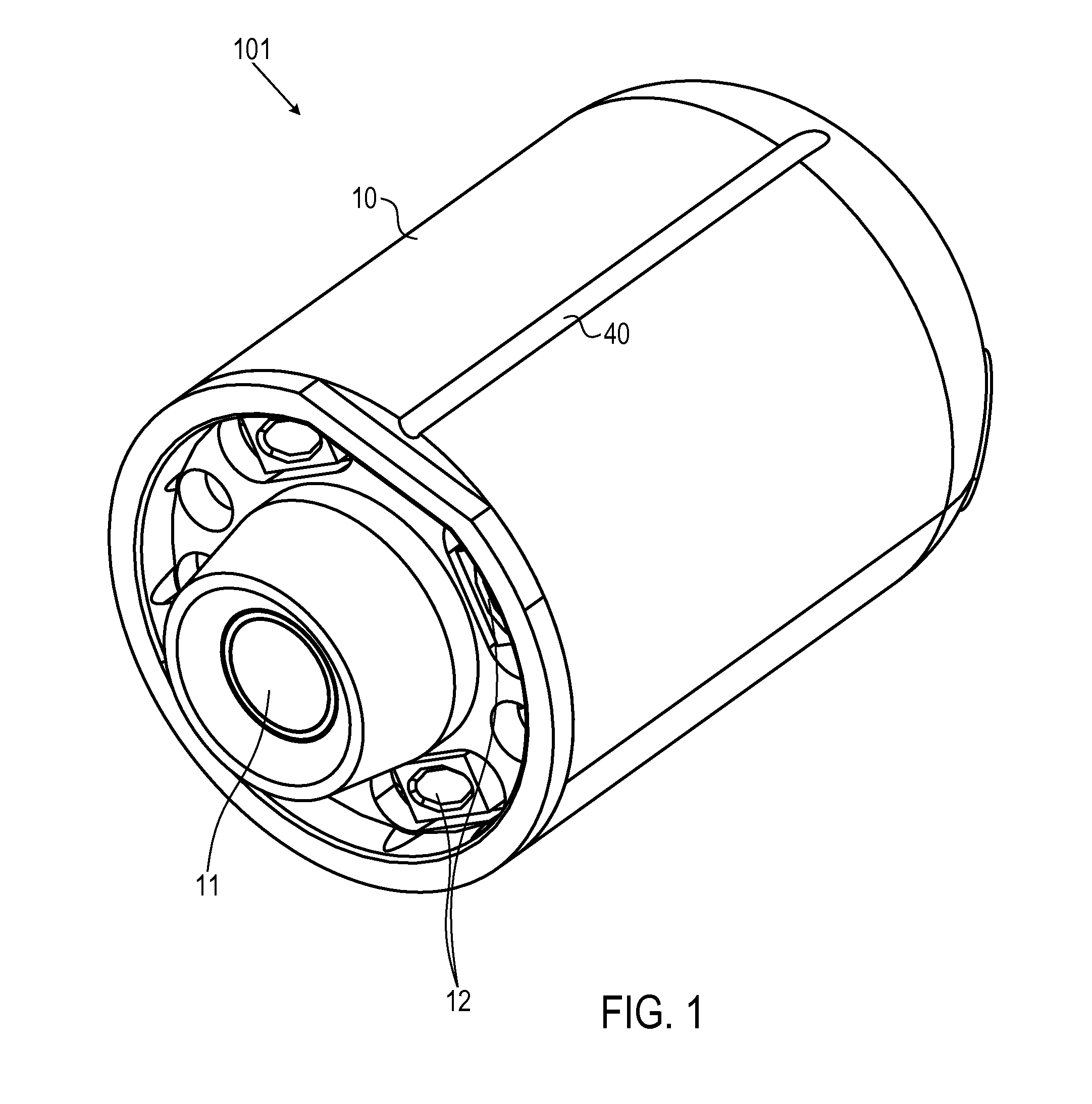
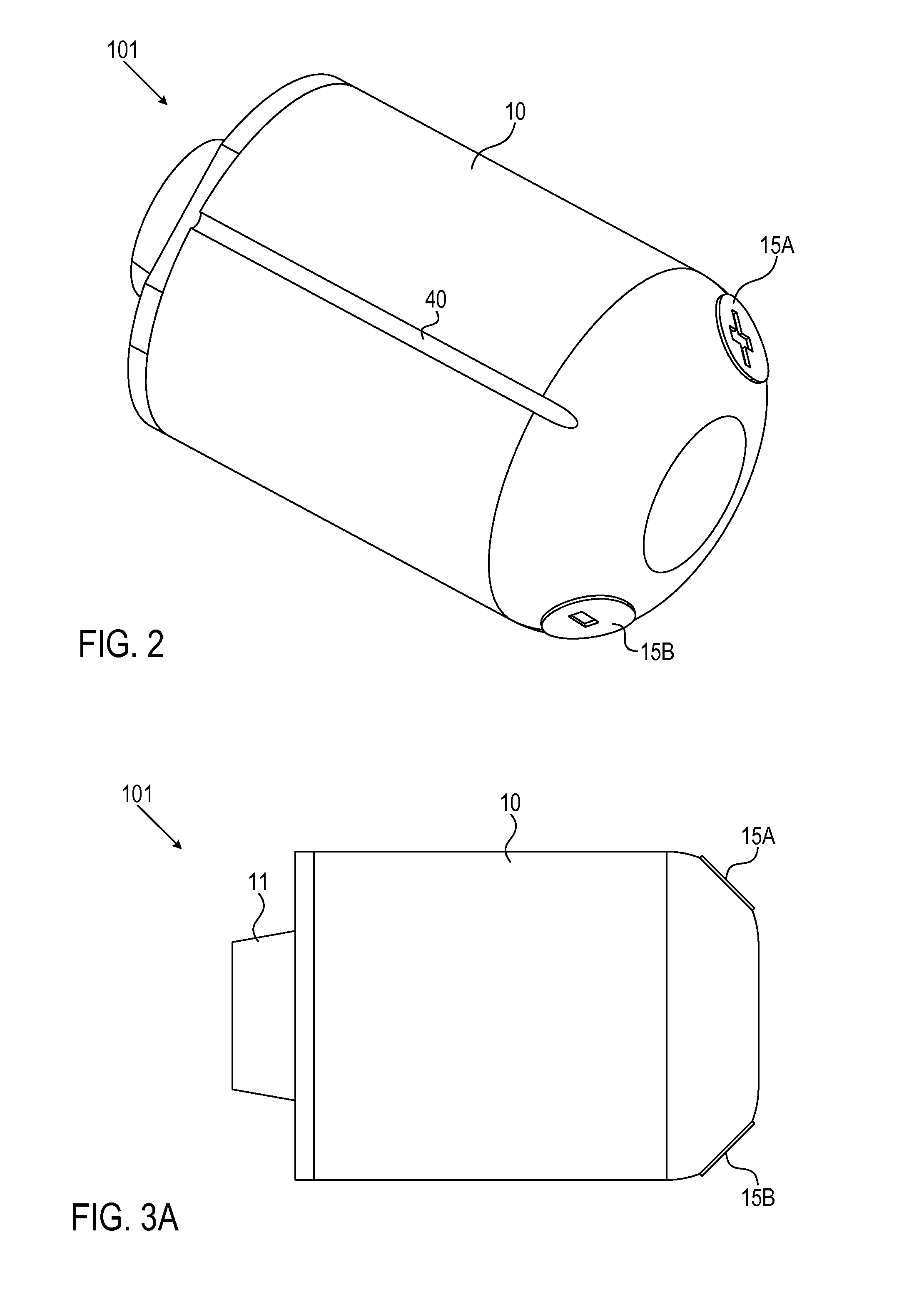
[0033]Reference is now made to FIG. 1, which illustrates a schematic front-side perspective view of an inner portion of an in-vivo device, which may be considered or is i...


PUM

PropertyMeasurementUnit
magnetic fieldsaaaaaaaaaa
magneticaaaaaaaaaa
frictionaaaaaaaaaa

Abstract

Reusable devices, systems and methods of assembly of reusable devices comprise an inner portion designed to be reused and an outer portion designed to be disposed. The reusable inner portion is a closed, self-contained receptacle comprising a housing, which encapsulates at least an imaging device, at least one illumination source, at least one rechargeable battery, and a controller. A first end of the closed reusable inner portion is covered by an optical system, and a second end of the closed reusable inner portion comprises battery contacts. The disposable outer portion comprises at least a shell and an optical dome. The housing of the reusable inner portion is inserted into the shell, and the optical dome is attached to the shell so as to detachably seal the reusable inner portion of the in-vivo device within the disposable outer portion of the device.

Description

FIELD OF THE INVENTION[0001]This application relates to the field of reusable in-vivo devices and systems, and methods of assembling reusable in-vivo devices.BACKGROUND OF THE INVENTION[0002]Swallowable capsule endoscopes are well-known devices that are used in order to acquire images of in-vivo lumens, e.g., the gastrointestinal (GI) tract. Nowadays, there is an on-going need for adding maneuvering capabilities to such capsules and to other in-vivo devices, and to thus provide the ability to perform various in-vivo operations at specific locations along the lumen that such devices travel. One method of maneuvering an in-vivo device while in-vivo is to use external magnetic fields, which may surround the patient being examined and / or treated by the in-vivo device and may control the location of the in-vivo device.[0003]An in-vivo device that may be externally controlled with regard to its in-vivo location and with regard to operations that the device may perform while in-vivo might ...

Claims


Application Information

Patent Timeline
Patent Type & Authority Applications(United States)
IPC IPC(8): A61B1/04A61B1/00
CPCA61B1/041A61B1/0011A61B1/00034A61B1/00103A61B1/00105A61B1/00142Y10T29/49826H04N23/555
Inventor SHAMIR, NACHUMGILAD, ZVIKA
Owner GIVEN IMAGING LTD
Why Eureka
Try Eureka