Prosthetic valve crimping device

a prosthetic valve and crimping technology, which is applied in the direction of prosthesis, forging/pressing/hammering apparatus, prosthesis, etc., can solve the problems of reducing the effectiveness of this type of device, and reducing the use range of the devi

Active Publication Date: 2009-05-12
EDWARDS LIFESCIENCES CORP
View PDF37 Cites 132 Cited by
  • Summary
  • Abstract
  • Description
  • Claims
  • Application Information

AI Technical Summary

Benefits of technology

[0014]In one preferred embodiment, the jaws are activated by the rotating mechanical member. The forces applied to the moveable jaws are predominantly in the radial direction. When crimping a stented valve in a symmetrical way, thus reducing its diameter, (as opposed to crushing and flattening) the radial forces are efficient and effective in evenly reducing the circumference of the prosthetic valve. Accordingly, the force applied to the jaws by the operator via an additional mechanical member is in the same vector and opposite to the stents reaction force while being crimped. This advantageously provides maximum efficiency to the crimping process.
[0015]Another preferred aspect is the use of a rotating plate including a spiral track, as the mechanical member, which translates the force of the operator, to the jaws. The gradually spiral-sloped track, in this case 225 degrees, reduces resistance to the crimping operation such that approximately 5 times less force is required by the operator than previous designs.
[0019]Another main aspect of the present invention is a novel design that allows activating the jaws by more than one contact point, this allows applying a smaller force to each contact point resulting in the possibility of making the part from relatively inexpensive plastic materials, thus helping to reduce the overall price of the product. Making the device inexpensive allows making the device disposable, which is an important aspect of the invention.
[0022]In another embodiment, a crimping mechanism includes a rotational member activated by a rotating handle and a pinion gear which allows rotating the member more than 360 degrees. The rotational member is activated by a lever handle and the stationary part is connected to a base. This configuration is advantageous for several reasons. For example, the arrangement allows a larger transmission ratio, and eliminates side forces on the whole apparatus resulting from the manual forces applied by the user, which tend to move the apparatus on the table. If the crimper is activated by two rotating members on both sides of the jaws, both members are connected by a bridge, which will restrict the possible movement of the handle to less than 360 degrees.
[0028]Another aspect of the present invention involves a method of selecting and utilizing a kit for preparing a prosthetic valve for use. The kit preferably includes a crimping mechanism and accessories such as, for example, a handle lever stop member, a balloon gauge, and / or a crimped-valve gauge. Each of the accessories is preferably removably attachable to the crimping mechanism. The stop member provides a physical stop to limit rotation of the lever handle. The crimped-valve gauge is preferably mounted adjacent to the crimping mechanism. After the prosthetic valve is crimped, the prosthetic valve is placed within the gauge to verify that its outer diameter is desirable. The balloon gauge provides a ring having an inner diameter calibrated to the desired maximum size of the expanded balloon used to deliver the prosthetic valve. The balloon gauge allows the operator to determine the amount of saline required to expand the balloon for proper deployment of the prosthetic valve in the patient.

Problems solved by technology

The drawback of this method is the contradiction created by the equation of 360 degrees divided by the number of jaws.
Therefore, the effectiveness of this type of device is substantially limited.
Due to the unique crimping requirements for stent-based prosthetic valves, it has been found that existing crimping devices configured for use with coronary stents are not suitable for use stent-based prosthetic valves.
In addition, as discussed above, existing crimping mechanisms suffer from a variety of shortcomings which limit their ability to be adapted for use with stent-based prosthetic valves.
Unfortunately, the pivoting design tends to concentrate stress in certain areas of the individual segments, and in the mechanism for pivoting them.
Also, the user must apply significant force to close the crimper aperture around a relatively large percutaneous heart valve.

Method used


Image

  • Prosthetic valve crimping device
  • Prosthetic valve crimping device
  • Prosthetic valve crimping device

Examples


Embodiment Construction

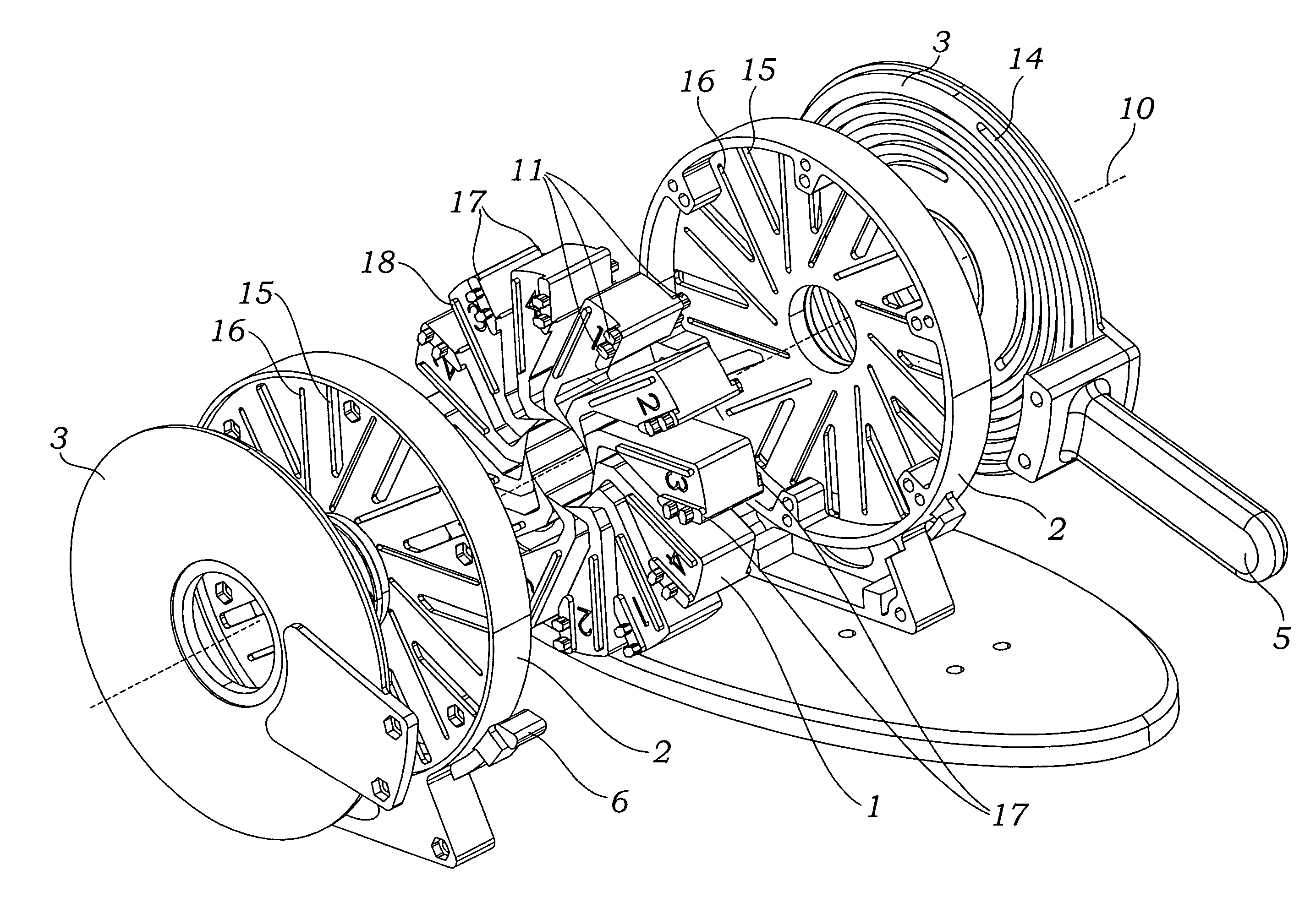
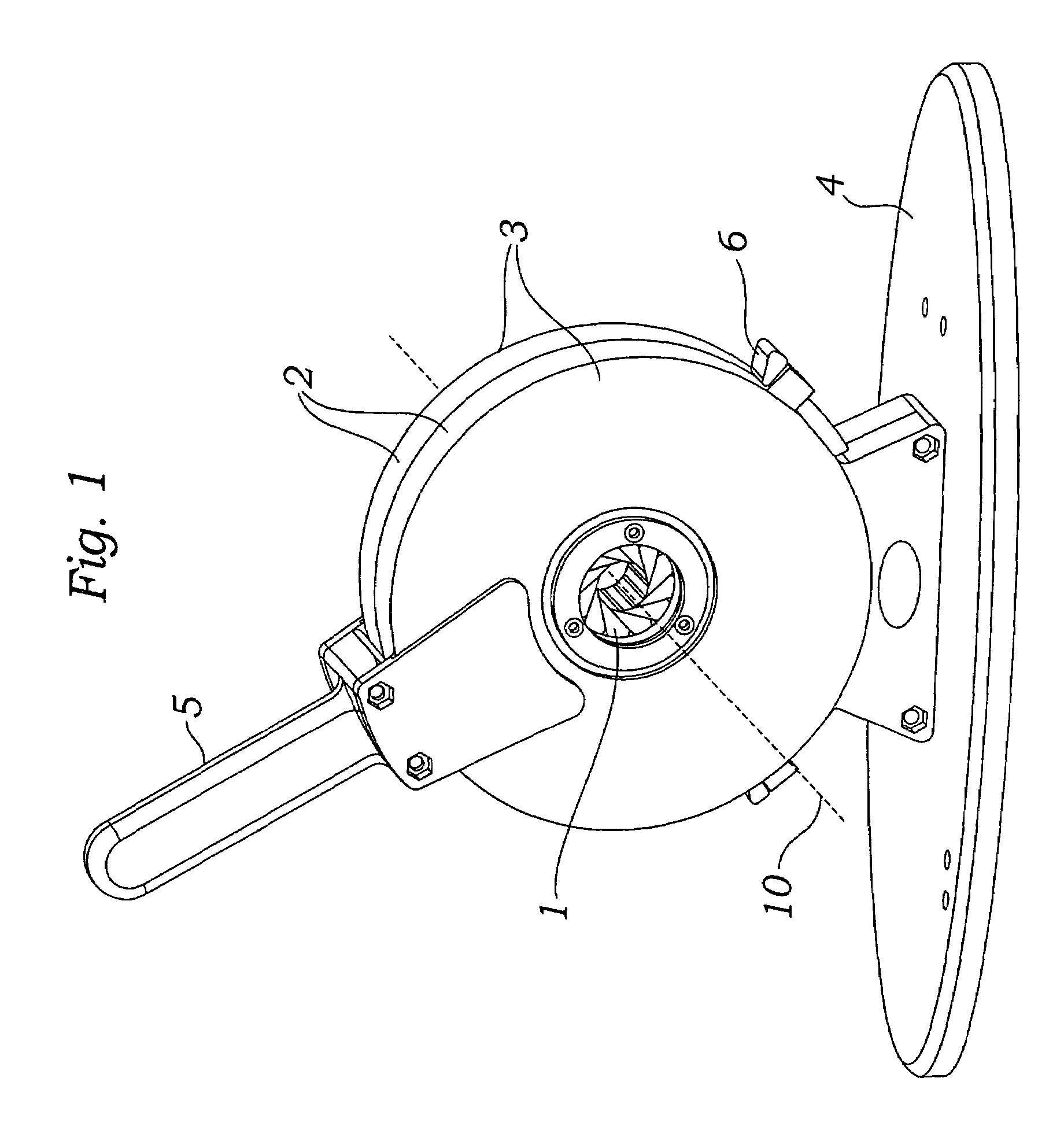
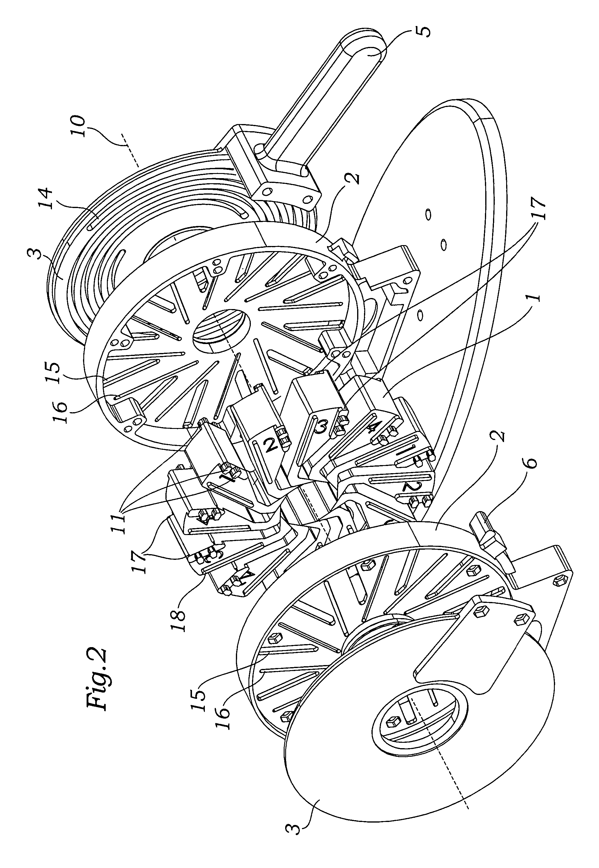
[0046]The present invention provides an improved crimper for stents or prosthetic valves. The particularly advantageous features of the present crimper enable reduction in diameter of relatively large stents or prosthetic valves. The crimper is especially suited for crimping prosthetic heart valves which have expanded diameters significantly larger than most stents currently in use. According to Chessa, et al., the Palmaz-Genesis XD stents (Cordis J&J Interventional Systems Co.) are designed for an expansion range of 10-18 mm, and are considered as either large or extra-large stents (see, Results and Mid-long-term Follow-up of Stent Implantation for Native and Recurrent Coarctation of the Aorta, European Heart Journal Volume 26, No. 24, Pp. 2728-2732, published online Sep. 26, 2005). The most frequently used stents are significantly smaller, in the 3-6 mm range. Crimpers for these stents have proved inadequate for reducing in size even larger prosthetic valves, such as the stented p...


PUM

PropertyMeasurementUnit
diameteraaaaaaaaaa
lengthaaaaaaaaaa
angleaaaaaaaaaa

Abstract

An improved crimping mechanism well-suited for use with stented prosthetic heart valves. The crimping mechanism includes a plurality of jaws configured for linear non-rotational movement toward a central axis. A rotational plate is formed with a plurality of spiral grooves or tracks for engaging the jaws. Rotational movement of the spiral tracks produces linear movement of the jaws. Nesting of the inner ends of the jaws permits each to be acted on along different radial lines while their inner faces move together evenly to reduce the crimping aperture in a smooth fashion. The crimping mechanism is particularly well-suited for use with stented prosthetic heart valves, such as a prosthetic aortic valve, though it can also be applied to other stented heart valves, venous valves, and even stent grafts which tend to be fairly large.

Description

RELATED APPLICATION[0001]The present application claims the benefit of priority under 35 U.S.C. §119(e) from provisional application No. 60 / 716,011, filed Sep. 9, 2005.BACKGROUND OF THE INVENTION[0002]1. Field of the Invention[0003]The present invention relates to a crimping device and, more particularly, to a device for crimping a stented prosthetic valve such as a heart valve from a large diameter to a smaller diameter.[0004]2. Description of the Related Art[0005]A stent is a generally cylindrical prosthesis introduced into a lumen of a body vessel via a catheterization technique. Stents may be self-expanding or balloon expandable. Balloon-expandable stents are typically crimped from an initial large diameter to a smaller diameter prior to advancement to a treatment site in the body. Before crimping, a balloon expandable stent is typically placed over an expandable balloon on a catheter shaft. In cases where the stent was manufactured in its fully crimped diameter, the stent is ex...

Claims


Application Information

Patent Timeline
Patent Type & Authority Patents(United States)
IPC IPC(8): B21D41/04
CPCA61F2/2412A61F2/2433B25B27/10A61F2/2475A61F2002/9522A61F2/9522A61F2/9524B30B7/04
Inventor SPENSER, BENJAMINBENICHOU, NETANEL
Owner EDWARDS LIFESCIENCES CORP
Why Eureka
Try Eureka