Flash memory backup system and method

Active Publication Date: 2006-09-07
WESTERN DIGITAL ISRAEL LTD
View PDF11 Cites 126 Cited by
  • Summary
  • Abstract
  • Description
  • Claims
  • Application Information

AI Technical Summary

Benefits of technology

[0022] Hence, improved speed performance and cost reduction is achieved. In pric

Problems solved by technology

Devices based on a NAND-type flash memory have certain limitations and must be handled in a specific manner.
One of these limitations is that a flash memory device may fail during a programming (write) operation.
When a programming failure occurs, a recovery algorithm must be activated, or the data may be lost.
However,

Method used


Image

  • Flash memory backup system and method
  • Flash memory backup system and method
  • Flash memory backup system and method

Examples


Embodiment Construction

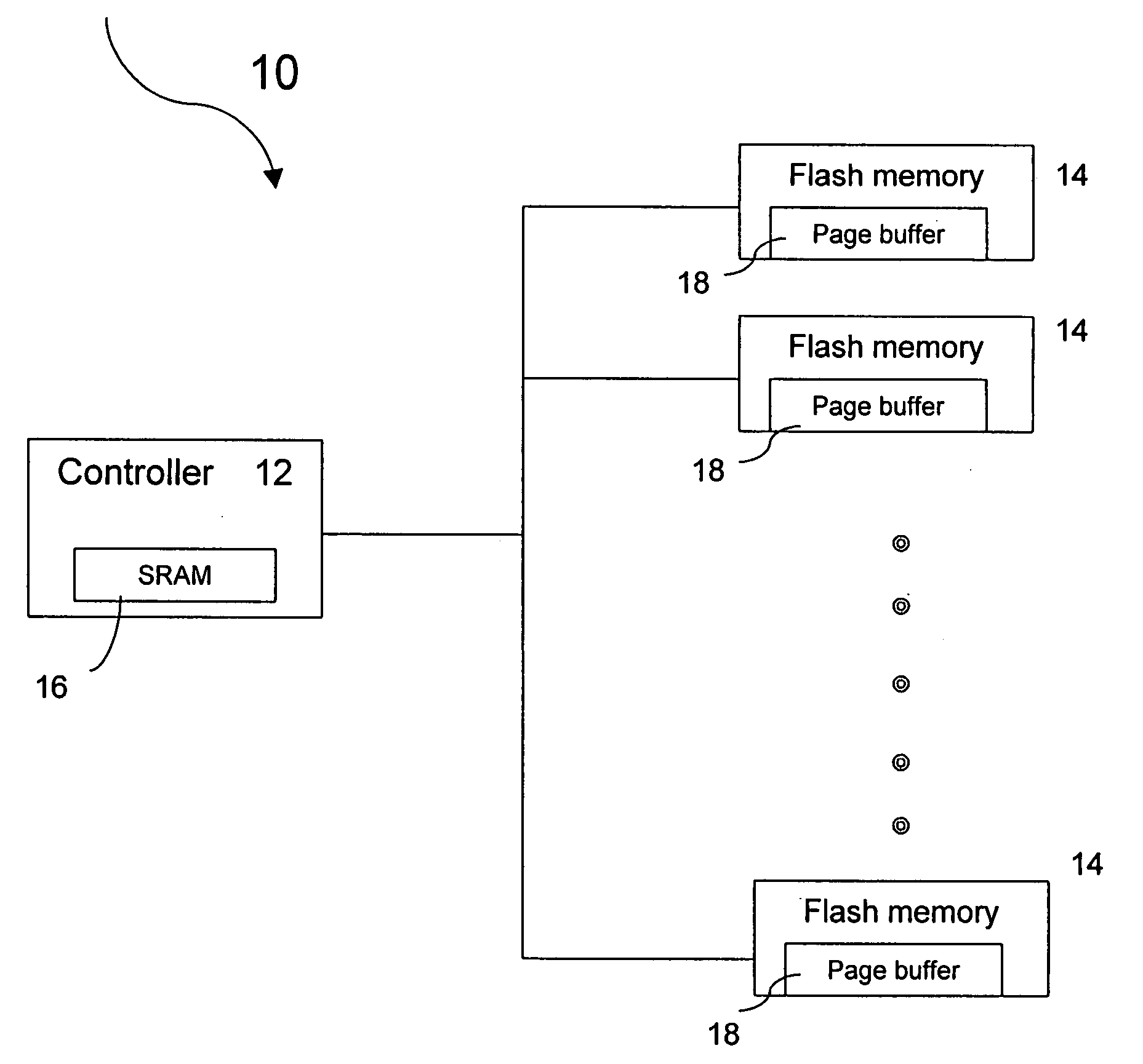
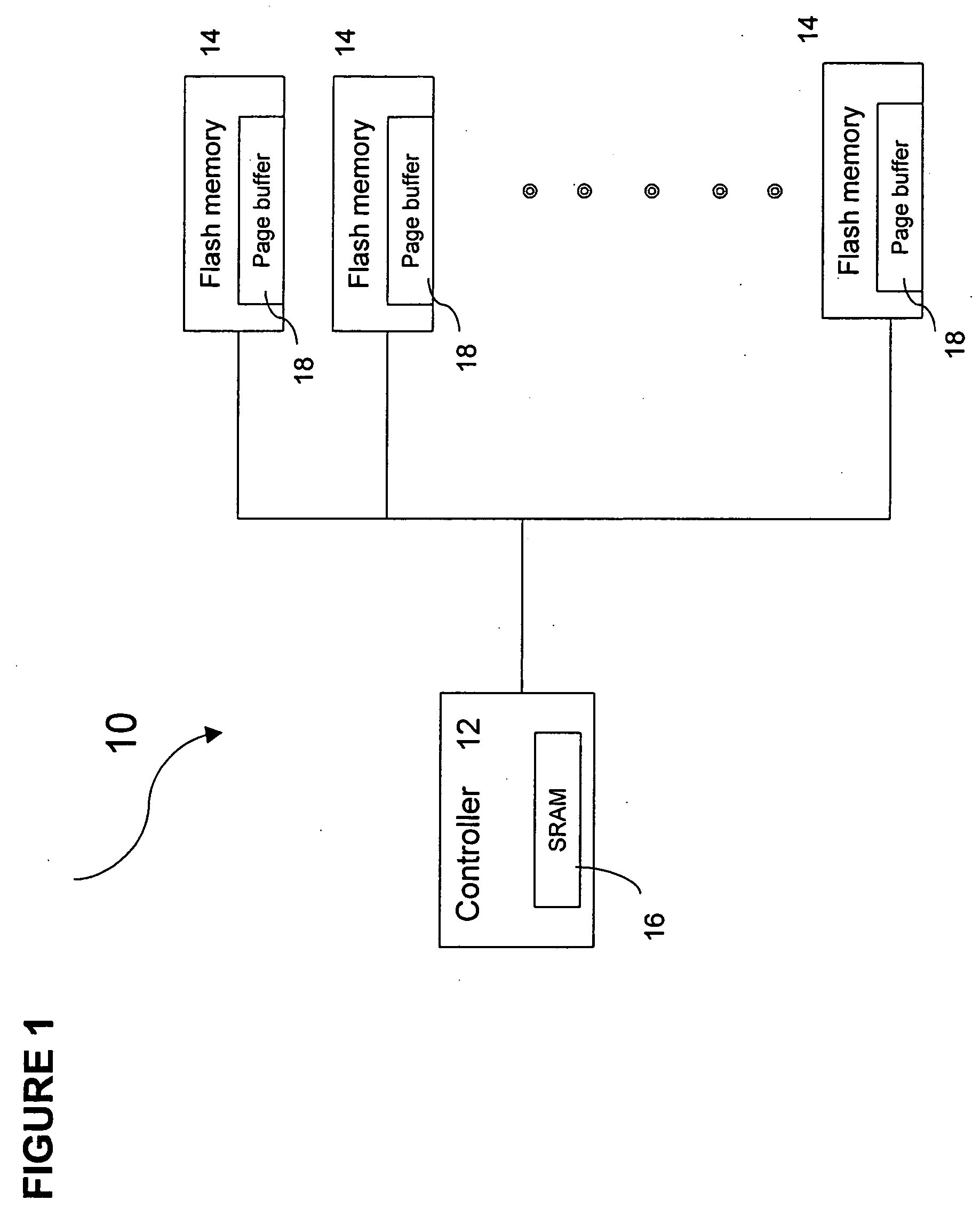
[0036] The present invention is a system and method for utilizing an area of memory for temporary storage on a page buffer of the flash memory device itself, rather than on the flash controller.

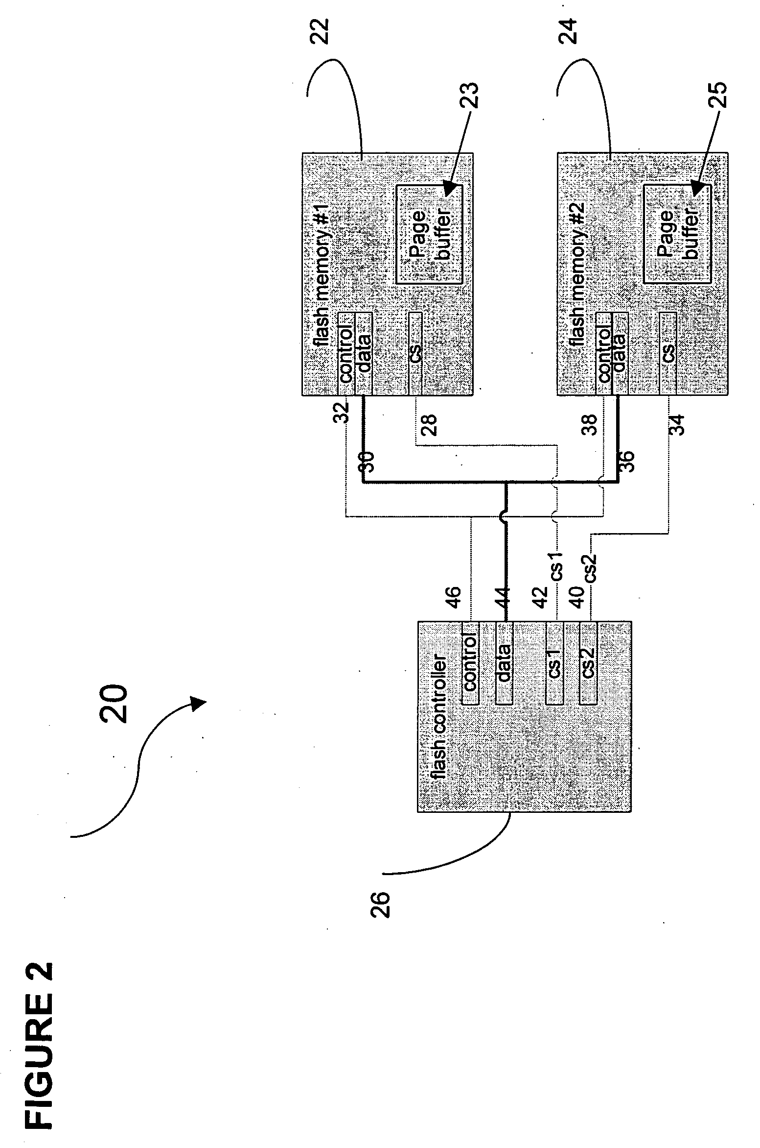
[0037] A preferred embodiment of the flash memory system of the present invention includes a flash controller for controlling operation of at least two flash memory devices. A page buffer is allocated within each flash memory device, such that a first page buffer functions as a designated target buffer and a second functions as a mirror buffer. The flash controller controls the transmission of data from the flash controller to the two page buffers and the programming of data from the designated target buffer to the non-volatile memory of the required flash memory device.

[0038] A mechanism for checking a programming failure to the designated target buffer is further provided. In the event of a programming failure, the page data is not lost, since a copy of the original page data is available...


PUM


Abstract

A flash memory system includes a flash controller for controlling operation of at least two flash memory devices. A page buffer is allocated within each flash memory device, such that one page buffer functions as a designated target buffer and another page buffer functions as a mirror buffer. The flash controller transmits the page data to two flash memory devices simultaneously, such that no backup of the page data is required to be kept in the flash controller. Hence, there is no delay in writing the next page data from a host computer to the flash controller.

Description

CROSS-REFERENCE TO RELATED APPLICATIONS [0001] This patent application claims the benefit of U.S. Provisional Patent Application No. 60 / 653,976, filed Feb. 18, 2005.FIELD OF THE INVENTION [0002] The present invention relates to the field of flash memory devices. More particularly, the present invention relates to storing data within a flash memory device. BACKGROUND OF THE INVENTION [0003] Storage media are an integral part of many electronic systems used today and is provided to serve a variety of purposes. The memory technology used for storage can be based on various technologies known in the art, e.g. magnetic discs, solid-state hard disks, etc. [0004] A solid-state disk technology commonly uses flash memory devices to store data. A flash memory device is a form of EEPROM (Electrically Erasable Programmable Read-Only Memory) that allows multiple memory locations to be erased or written in one programming operation. In lay terms, it is a form of rewritable memory chip that, unlik...

Claims


Application Information

Patent Timeline
IPC IPC(8): G11C11/34G11C16/04
CPCG11C11/005G11C16/10G11C16/16G11C2216/14
Inventor EREZ, ERAN
Owner WESTERN DIGITAL ISRAEL LTD
Why Eureka
Try Eureka