
Leadless intra-cardiac medical device with reduced number of feed-thrus

Active Publication Date: 2013-12-26
PACESETTER INC
View PDF1 Cites 125 Cited by
  • Summary
  • Abstract
  • Description
  • Claims
  • Application Information

AI Technical Summary

Benefits of technology

The patent describes a leadless implantable medical device (LIMD) that can be implanted in the heart. The device includes a housing with a battery case and an end cap. The end cap has an open end and a proximal end. The battery case has a terminal end and forms a common electrode with the end cap. The device also includes first and second electrodes that are connected to the battery case and the end cap, respectively. The device can deliver therapy and sense or stimulate tissue in the heart. The method for implanting the device involves mechanically securing the battery case to the end cap with a non-conductive coupler and joining the first electrode to the end cap. The second electrode is connected to the battery case and the end cap. The method can also involve using the end cap as a common electrode and delivering therapy to atrial or ventricular tissue. The device can be insulated from heart tissue to isolate the battery case. The technical effects of the patent include providing a leadless implantable medical device that can be implanted in the heart and deliver therapy without the need for a lead.

Problems solved by technology

The leads may experience certain limitations, such as incidences of venous stenosis or thrombosis, device-related endocarditis, lead perforation of the tricuspid valve and concomitant tricuspid stenosis; lacerations of the right atrium, superior vena cava, and innominate vein or pulmonary embolization of electrode fragments during lead extraction.
However, the LIMDs proposed thus far exhibit certain limitations.
The use of multiple feed-thrus increases the cost and size of the LIMD.

Method used


Image

  • Leadless intra-cardiac medical device with reduced number of feed-thrus
  • Leadless intra-cardiac medical device with reduced number of feed-thrus
  • Leadless intra-cardiac medical device with reduced number of feed-thrus

Examples


Embodiment Construction

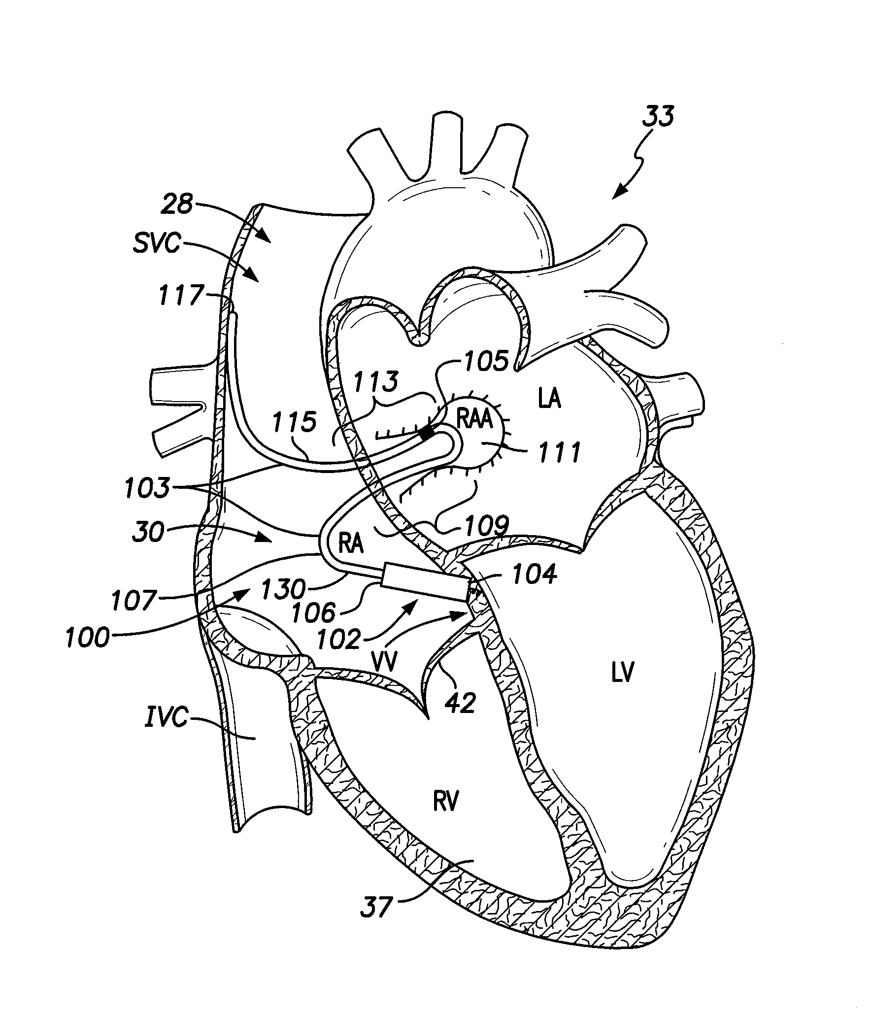
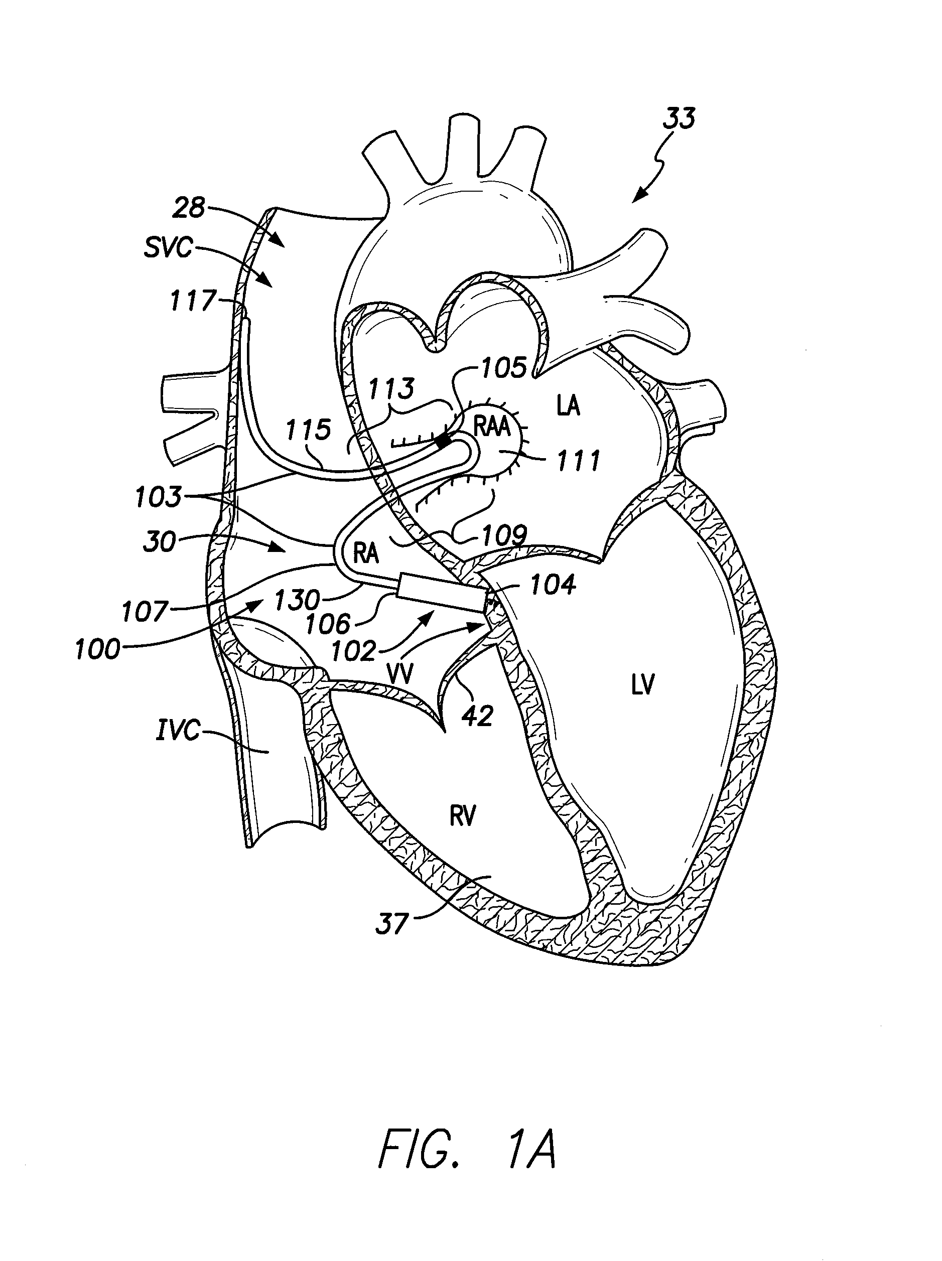
[0024]FIG. 1A illustrates a sectional view of a patient's heart 33 and shows an LIMD 100. The LIMD 100 may have been placed through the superior vena cava (SVC) 28 or inferior vena cava (IVC) into the right atrium 30 of the heart 33. The LIMD 100 comprises a housing 102 configured to be implanted entirely within a single local chamber of the heart. The housing 102 includes a proximal base end 104 and a distal top end 106. The proximal base end 104 includes an active fixation member, such as a helix, that is illustrated to be implanted in the ventricular vestibule (VV). A shaped intra-cardiac (IC) device extension 103 extends from the distal top end 106 of the housing 102. The IC device extension 103 comprises an elongated body that may be tubular in shape and may include a metal braid provided along at least a portion of the length therein. The extension body may include a transition sub-segment, an active interim-segment and a stabilizer end-segment, all of which are illustrated in...


PUM

PropertyMeasurementUnit
aaaaaaaaaa

Abstract

A leadless implantable medical device (LIMD) includes a housing formed from a battery and an end cap. A proximal end of the end cap forms an LIMD proximal end and a distal end of the battery case forms an LIMD distal end. A non-conductive coupler mechanically secures a terminal end of the battery case to a mating end of the end cap, while maintaining the battery case and end cap electrically separated. A first electrode projects from the proximal end of the end cap. An intra-cardiac (IC) device extension projects from the distal end of the battery case. The extension includes a second electrode that is electrically connected to the battery case. The second electrode is located remote from the LIMD distal end. An electronics module is located within an internal cavity of the end cap and communicates with the first and second electrodes.

Description

FIELD OF THE INVENTION[0001]Embodiments of the present invention generally relate to leadless implantable medical devices, and more particularly to leadless intra-cardiac medical devices with a reduced number of feed-thrus. As used herein, the term “leadless” generally refers to an absence of electrically-conductive leads that traverse vessels or other anatomy outside of the intra-cardiac space, while “intra-cardiac” means generally, entirely within the heart and associated vessels, such as the SVC, IVC, CS, pulmonary arteries and the like.BACKGROUND OF THE INVENTION[0002]Currently, permanently-implanted pacemakers (PPMs) utilize one or more electrically-conductive leads (which traverse blood vessels and heart chambers) in order to connect a canister with electronics and a power source (the can) to electrodes affixed to the heart for the purpose of electrically exciting cardiac tissue (pacing) and measuring myocardial electrical activity (sensing). The leads may experience certain l...

Claims


Application Information

Patent Timeline
IPC IPC(8): A61N1/375
CPCA61N1/3756A61N1/368Y10T29/49002A61N1/362
Inventor DIANATY, ALIMOUCHAWAR, GABRIEL A.BORNZIN, GENE A.POORE, JOHN W.MIN, XIAOYISOMOGYI, ZOLTANWILLIAMSON, RICHARD
Owner PACESETTER INC
Features
  • Generate Ideas
  • Intellectual Property
  • Life Sciences
  • Materials
  • Tech Scout
  • Unparalleled Data Quality
  • Higher Quality Content
  • 60% Fewer Hallucinations
Learn More