Double sided hand hack saw blade and method of manufacture

a hack saw blade and double-sided technology, applied in the field of hack saw blades, can solve the problems of single cutting edge wear, wear out faster than desired, and inability to meet the needs of use, and achieve the effects of uniform tooth wear, improved cutting efficiency and tooth wear

Active Publication Date: 2014-01-02
BLACK & DECKER INC
View PDF18 Cites 10 Cited by
  • Summary
  • Abstract
  • Description
  • Claims
  • Application Information

AI Technical Summary

Benefits of technology

[0024]One advantage of the present invention is that the double-sided blade will provide increased, about double, the blade life as compared to single-sided hack saw blades. Another advantage of the present invention is that the timing of the teeth along the first and second cutting edges will aid in stabilizing the blade, resulting in better cutting efficiency and tooth wear, and improved quality of the cut. Another advantage is that setting the teeth on opposite sides of the blade to substantially the same maximum set magnitude, and locating the points of maximum set magnitude on opposite sides of the blade so they are either timed with each other or about 180 degrees out of phase with each other, provides uniform tooth wear and can significantly improve blade life in comparison to prior art blades.
[0025]Other objects and advantages of the present invention, and / or of the currently preferred embodiments thereof, will become more readily apparent in view of the following detailed description of the currently preferred embodiments and accompanying drawings.

Problems solved by technology

Because typical prior art hack saw blades include only a single cutting edge, fundamental limitations persist.
The single cutting edge can wear out, or wear out quicker than desired, or even fracture, thereby requiring disposal of the entire blade.
The cost of manufacture and materials may also be unnecessarily high for only a single cutting edge.
However, while one might expect that a double sided hack saw blade would provide about double the blade life, this is often not the case.
In addition, the blade can fracture prior to the second-used side wearing out.

Method used


Image

  • Double sided hand hack saw blade and method of manufacture
  • Double sided hand hack saw blade and method of manufacture
  • Double sided hand hack saw blade and method of manufacture

Examples


Embodiment Construction

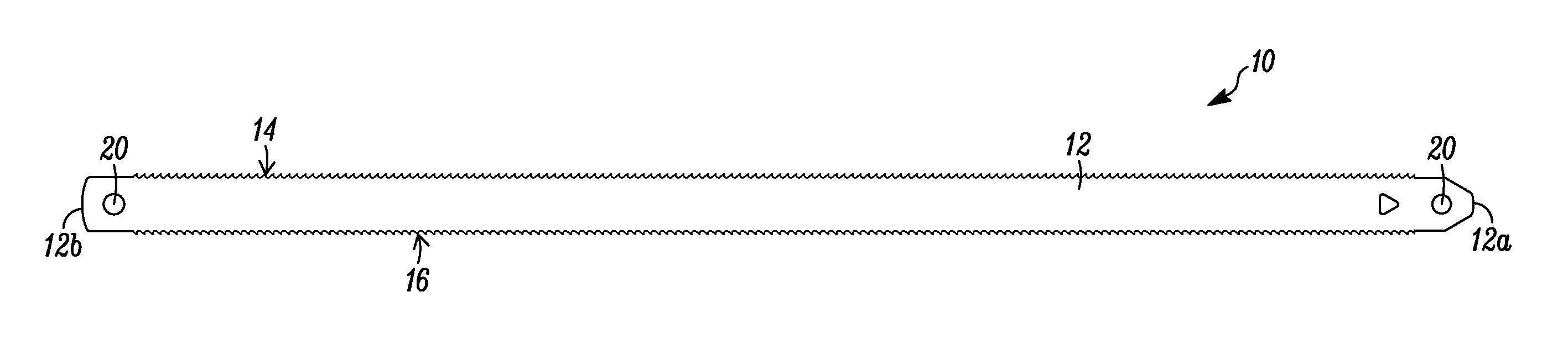
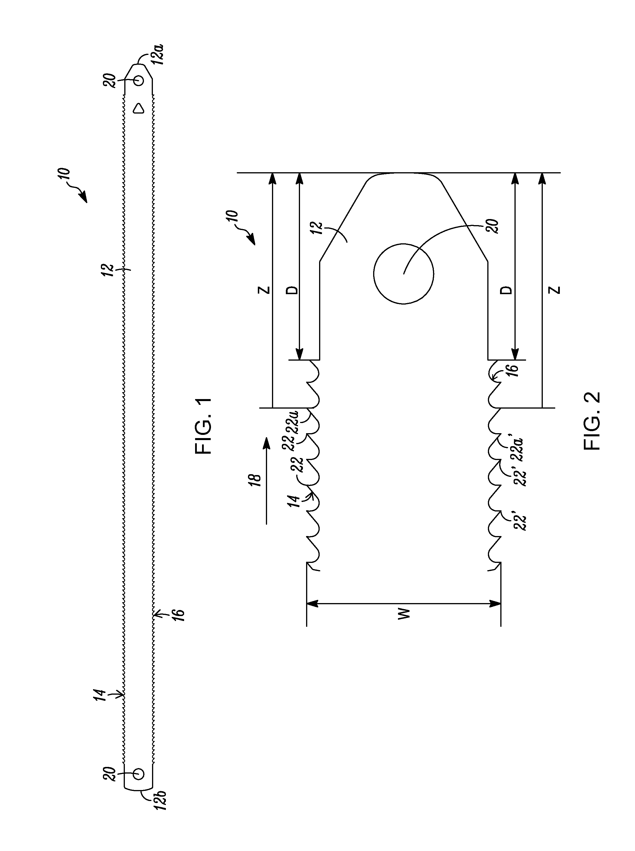
[0031]In FIGS. 1 and 2, a double-sided hand hacksaw blade is indicated generally by the reference numeral 10. The blade 10 includes a blade body 12, defining a first end 12a and a second end 12b. The blade 10 further defines a first cutting edge 14 defined by a plurality of teeth 22 extending along one side of the blade body 12 between the first and the second ends 12a, 12b of the blade body, and a second cutting edge 16 defined by a plurality of teeth 22′ located on the opposite side of the blade body 12 relative to the first cutting edge 14. In the illustrated embodiment, and as described further below, the first and second cutting edges 14, 16 extend along substantially the entire length of the blade body 12, i.e., from approximately one end of the blade body 12a to the opposite end of the blade body 12b. The first and second cutting edges 14, 16 define a cutting direction indicated by the first arrow 18. As may be recognized by those of ordinary skill in the pertinent art based ...


PUM

PropertyMeasurementUnit
thicknessaaaaaaaaaa
thicknessaaaaaaaaaa
thicknessaaaaaaaaaa

Abstract

A double-sided saw blade, such as a hack saw blade, comprising a blade body defining a first end and a second end; a first cutting edge located on one side of the blade body defining a first cutting tooth set pattern and a second cutting edge located on an opposite side of the blade body defining a second cutting tooth set pattern; wherein the first set pattern and the second set pattern are (i) timed with respect to one another or (ii) 180 degrees out of phase with respect to one another. A first tooth of the first set pattern may be indexed relative to a designated reference point along the blade body and a first tooth of the second set pattern may be equally indexed relative to the same designated reference point along the blade body.

Description

CROSS REFERENCE TO RELATED APPLICATIONS[0001]This application claims the benefit under 35 U.S.C. §119(e) of similarly-titled U.S. Provisional Application No. 61 / 666,724, filed Jun. 29, 2012, the content of which is incorporated by reference in its entirety as if fully set forth herein.FIELD OF THE INVENTION[0002]The present invention relates to saw blades, and more particularly, to hand hack saw blades having cutting edges on both sides of the blade.BACKGROUND OF THE INVENTION[0003]Typical prior art hack saw blades include a blade body having a single cutting edge defined by a plurality of teeth axially spaced relative to each other along one side of the blade body, and a non-working edge formed on an opposite side of the blade body relative to the cutting edge. Because typical prior art hack saw blades include only a single cutting edge, fundamental limitations persist. The single cutting edge can wear out, or wear out quicker than desired, or even fracture, thereby requiring dispo...

Claims


Application Information

Patent Timeline
Patent Type & Authority Applications(United States)
IPC IPC(8): B23D61/12B23P15/28
CPCB23D61/126B23P15/28B23D61/121B23D65/04
Inventor NOVAK, JOSEPH T.KORB, WILLIAM B.
Owner BLACK & DECKER INC
Why Eureka
Try Eureka