High Strength Upper Receiver System and Method for Modular Rifle

a modular rifle and upper receiver technology, applied in the field of high-strength upper receiver system and modular rifle field, can solve the problems of shortening the life cycle of aluminum upper receiver and rifle system, material wear, and deterioration of aluminum material of upper receiver, and achieve the effect of longer operating life and high reliability

Active Publication Date: 2014-01-02
THE OTIS PATENT TRUST
View PDF25 Cites 56 Cited by
  • Summary
  • Abstract
  • Description
  • Claims
  • Application Information

AI Technical Summary

Benefits of technology

[0005]In some embodiments, among others, to secure the liner inside the upper receiver assembly and keep the liner from rotating within the upper receiver assembly during firing of the rifle, screws or pins are inserted into a flange on each side of the upper receiver assembly adjacent to the opening on the forward face of the upper receiver. The screws or pins impinge the liner on both sides of the liner through grooves machined in the outside of the liner, thereby preventing rotational movement of the liner and traveling of the liner along the longitudinal axis of the barrel and upper receiver assemblies during firing of the rifle. In this manner, the liner remains properly and securely attached within the upper receiver assembly of the rifle system and provides a secure attachment point for the barrel assembly.
[0006]In some embodiments, among others, the insertion of the hardened metal liner within the upper receiver assembly allows for a strengthened chamber housing the operation of the bolt carrier system, providing higher reliability and longer operating life of the upper receiver assembly and rifle system.

Problems solved by technology

While machining the upper receiver from a solid billet of aluminum may offer added strength over forging of the receiver, the aluminum material of the upper receiver is nevertheless subject to degradation and deformation to the high gas temperatures and operation of the bolt carrier system inside the upper receiver.
Friction created by repeated operation of a steel bolt carrier system within an aluminum upper receiver usually causes material wear and shortens the life cycle of the aluminum upper receiver and rifle system.

Method used


Image

  • High Strength Upper Receiver System and Method for Modular Rifle
  • High Strength Upper Receiver System and Method for Modular Rifle
  • High Strength Upper Receiver System and Method for Modular Rifle

Examples


Embodiment Construction

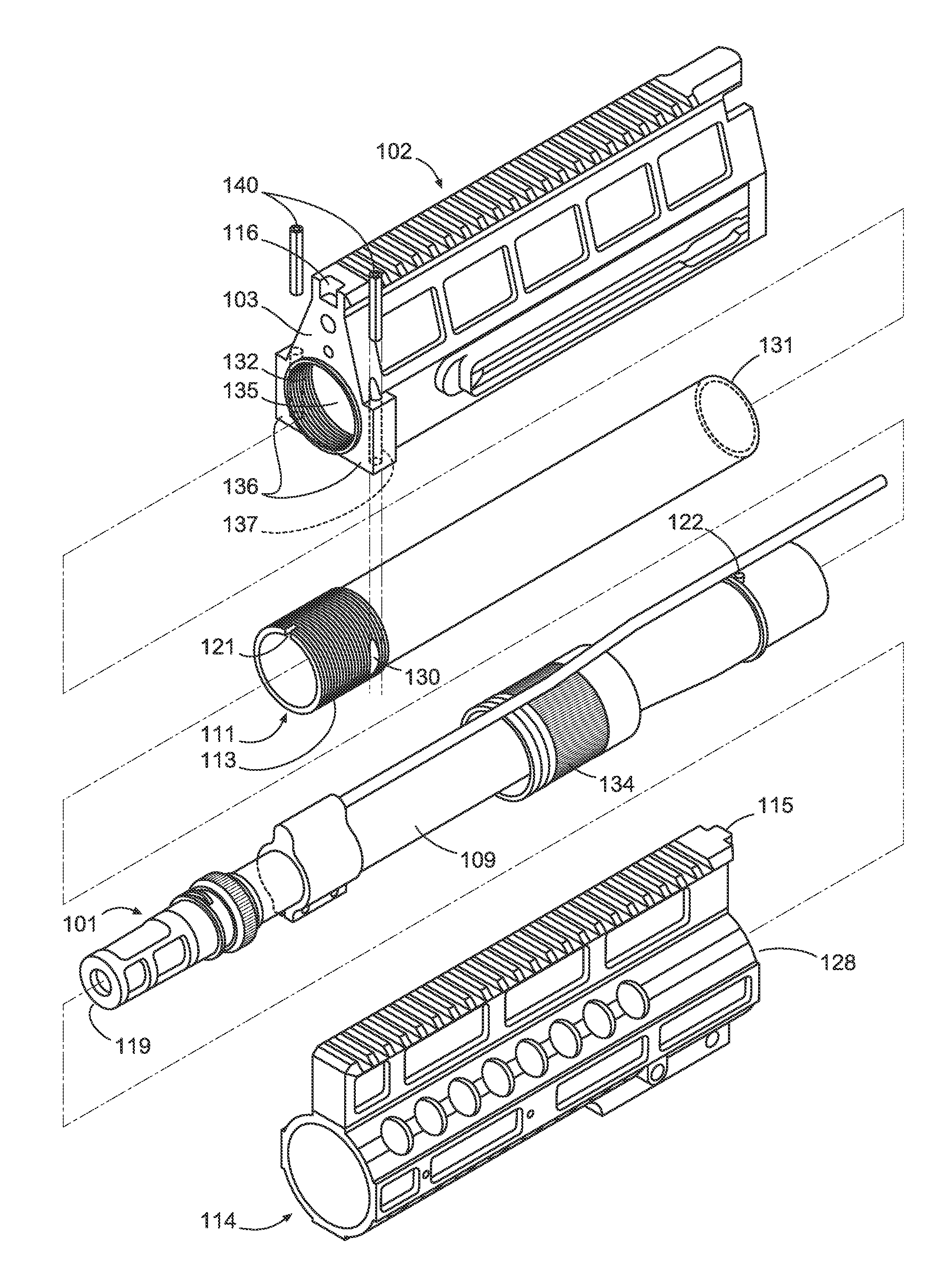
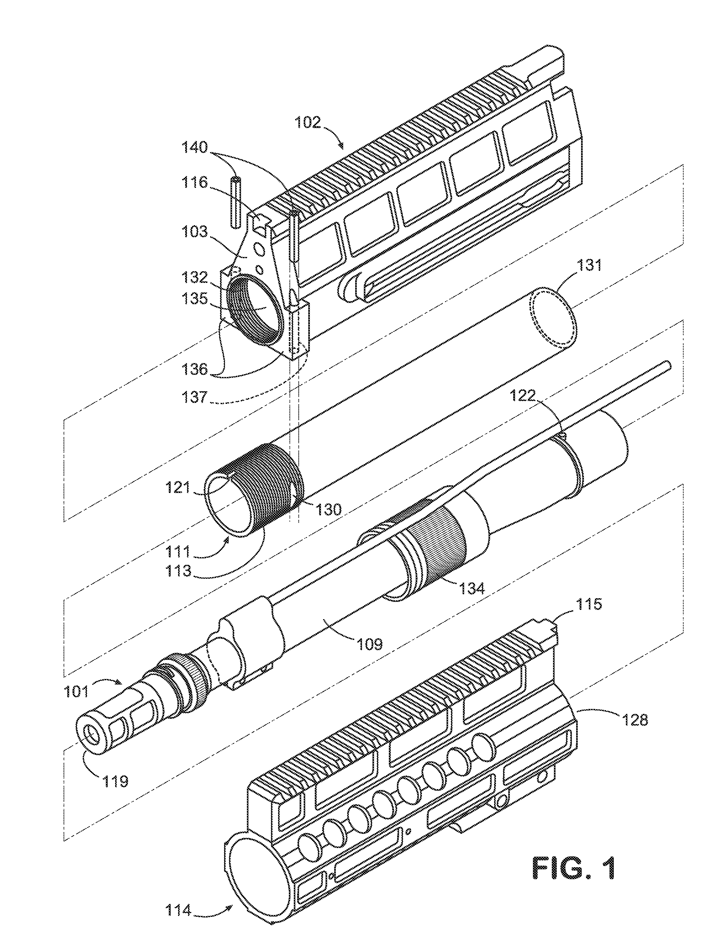
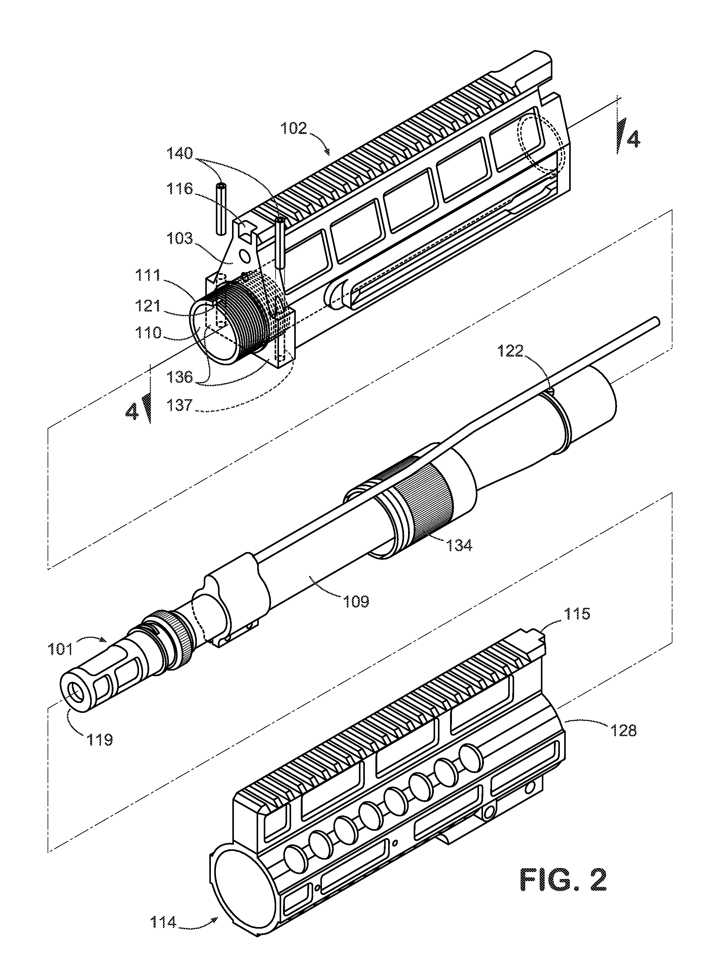
[0013]Disclosed below are embodiments of a high-strength upper receiver system and method for a modular rifle system.

[0014]FIG. 1 is a perspective view of a fore 114 and aft 102 portions of an upper receiver assembly, a barrel assembly 101, and a liner insert 110 in accordance with one exemplary embodiment of the present invention.

[0015]With reference to FIG. 1, aft portion 102 of upper receiver assembly comprises a front face 103 at its fore end 111 containing a circular aperture 135 and two flanges 136 on either side of aperture 135. Aperture 135 contains machined threads 132 along its inner diameter. Flanges 136 each contain a vertical pin insert channel 137. Liner insert 110 may be comprised of stainless steel or another hardened metal composition and contains circumferential machined threads 113 on its fore end 111 and machined indentations 130 on each of two opposing sides of its outside circumference.

[0016]With reference to FIG. 1, aft end 131 of liner insert 110 is inserted ...


PUM


Abstract

A modular rifle includes an upper receiver assembly and a barrel assembly. The upper receiver, typically fashioned from aluminum, can be strengthened by insertion of a hardened metal liner insert inside the aft portion of the upper receiver. The upper receiver liner insert is secured within the aft portion of the upper receiver assembly by engaging screw threads on the liner insert with receiving threads inside the aft portion of the upper receiver and insertion of anchor pins into the aft portion of the upper receiver. The anchor pins impinge the liner insert such that it is prevented from rotating within the upper receiver. The barrel assembly is attached to the liner insert by engaging screw threads on the liner insert with threads within a barrel nut connector sleeve.

Description

BACKGROUND OF THE INVENTION[0001]A rifle is a type of weapon that fires rounds. Typically, the rifle includes a trigger, a hammer, and a barrel. The round is positioned in the barrel, and, when the trigger is pulled, the hammer fires the round through the barrel. A modular rifle typically includes a lower receiver assembly, an upper receiver assembly housing the barrel, and a coupling mechanism. The M-16 style rifle is a type of modular rifle system commonly used by military and police forces that features a gas-operated bolt and bolt carrier system, as disclosed, for example, in U.S. Pat. No. 2,951,424, issued to Eugene M. Stoner on Sep. 6, 1960 (incorporated herein by reference in its entirety). The AR-15 style rifle is a similarly designed modular rifle system commonly sold and used in civilian applications.[0002]For most M-16 / AR-15 style rifle systems, the upper receiver is fashioned out of forged lightweight aluminum on account of its machinability and corrosion resistance. Whi...

Claims


Application Information

Patent Timeline
Patent Type & Authority Applications(United States)
IPC IPC(8): F41A3/66F41A11/02
CPCF41A3/66F41A11/02F41C23/16
Inventor PATEL, SWETAL K.
Owner THE OTIS PATENT TRUST
Why Eureka
Try Eureka