Burner, combustion apparatus, method for combustion, method for controlling combustion, recording medium, and water heater

a combustion apparatus and burner technology, applied in the field of burners and combustion apparatuses, can solve the problems of reducing thermal efficiency and requiring stab supply of air-fuel mixtures

Active Publication Date: 2014-01-02
PURPOSE CO LTD
View PDF7 Cites 25 Cited by
  • Summary
  • Abstract
  • Description
  • Claims
  • Application Information

AI Technical Summary

Benefits of technology

[0007]Burner combustion includes high intensity combustion and low intensity combustion. In low intensity combustion with a burner using a metal knit, the flow-out rate of an air-fuel mixture is held down, and the difference between the flow rate and the combustion rate is small. Thus, a

Problems solved by technology

The problem in a case where the flame holding function is feeble is that flames lift-off and it is conspicuous to decrease the thermal efficiency, to emit excess carbon

Method used


Image

  • Burner, combustion apparatus, method for combustion, method for controlling combustion, recording medium, and water heater
  • Burner, combustion apparatus, method for combustion, method for controlling combustion, recording medium, and water heater
  • Burner, combustion apparatus, method for combustion, method for controlling combustion, recording medium, and water heater

Examples


Embodiment Construction

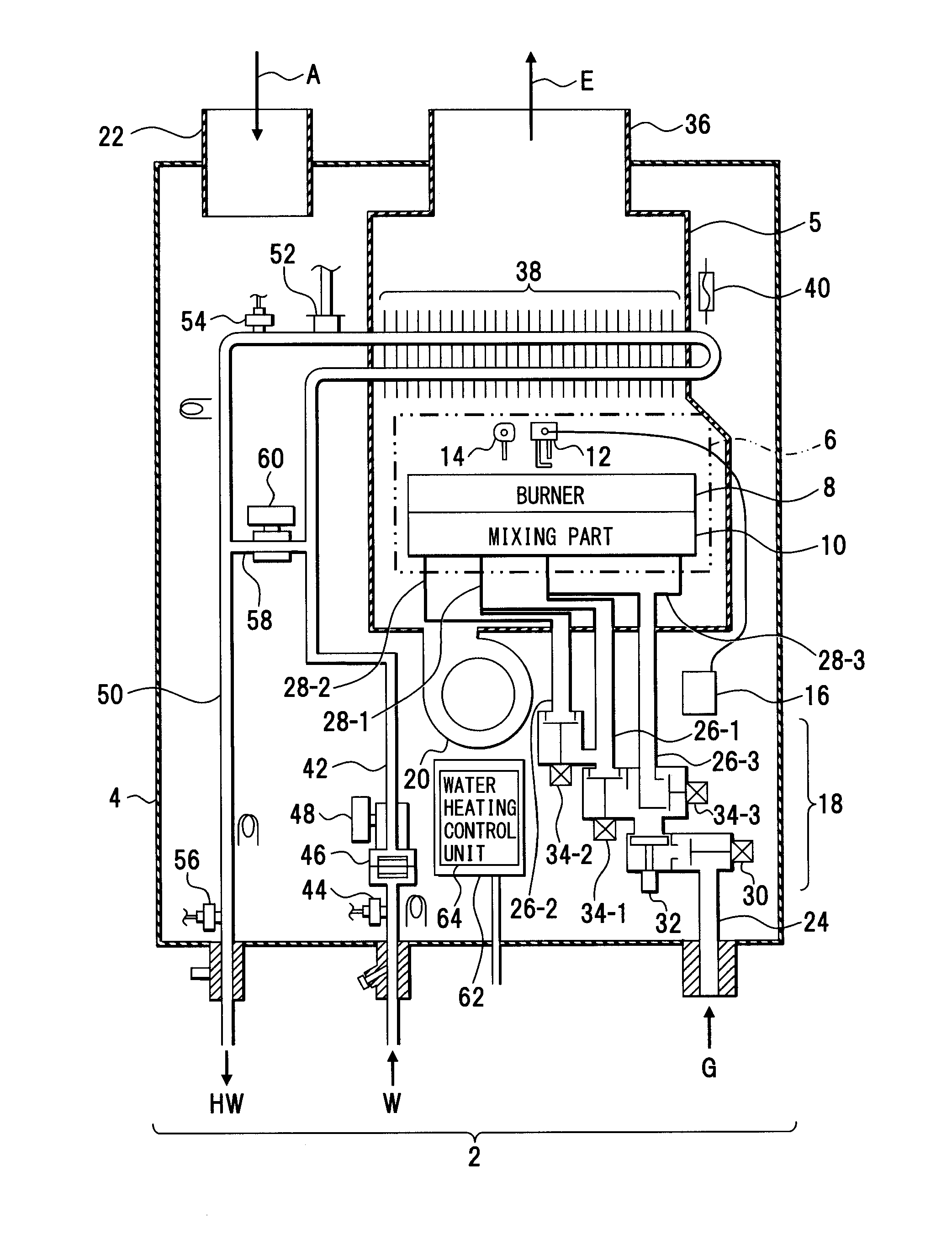
[0056]FIG. 1 depicts one example of a water heater. A structure depicted in each drawing, as well as that in FIG. 1, is an example, and the present invention is not limited to such a structure.

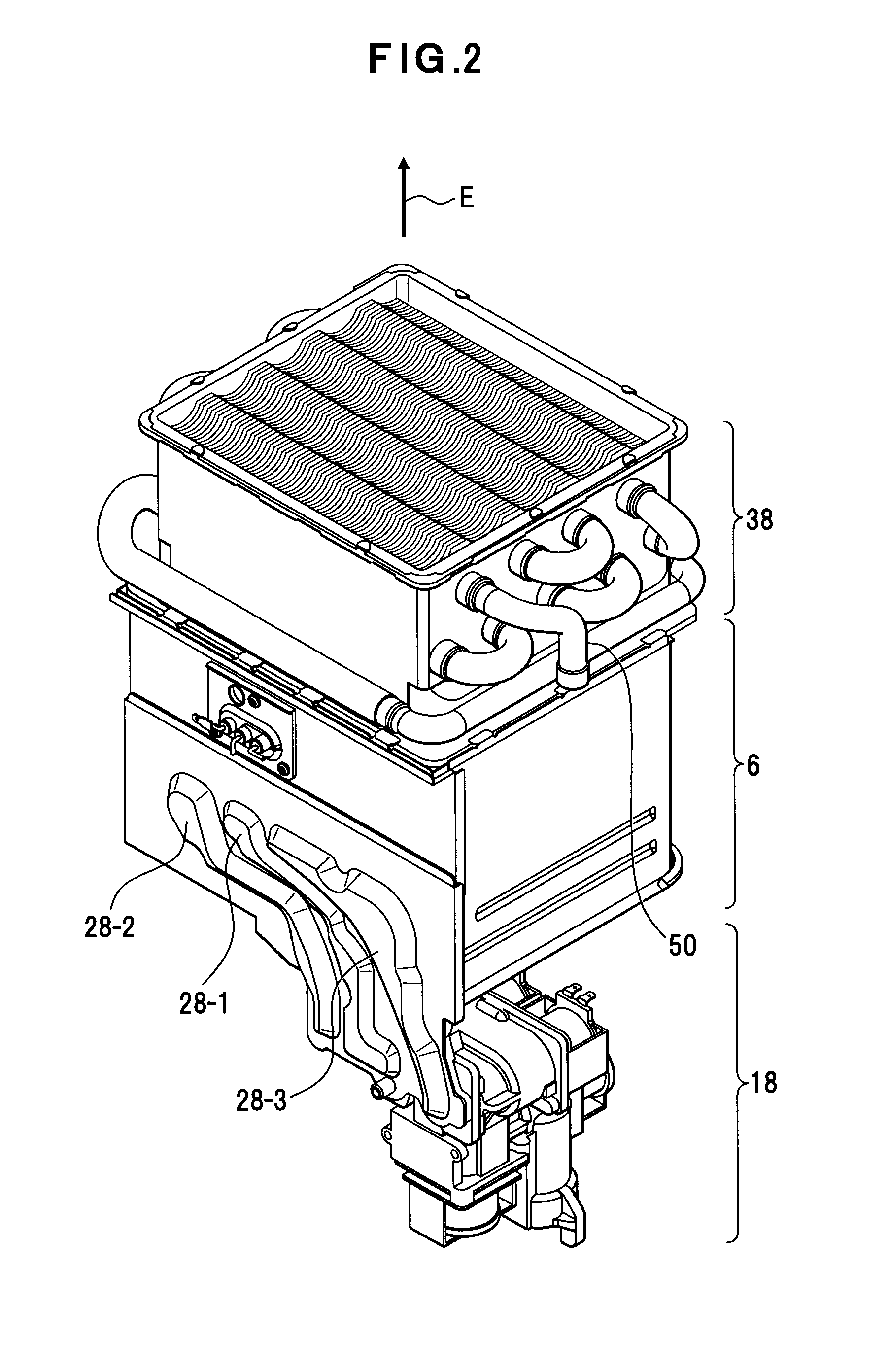
[0057]A housing 4 is provided for this water heater 2. A heat exchanger housing 5 is disposed in this housing 4. A combustion chamber 6 is included in this heat exchanger housing 5. A burner 8 that combusts an air-fuel mixture GA is disposed in this combustion chamber 6. The burner 8 is an example of a combustion apparatus for the air-fuel mixture GA. This burner 8 is divided into a plurality of burner parts 8-1, 8-2, 8-3, 8-4 and 8-5 (FIG. 15).

[0058]A spark plug 12 as an example of an ignition means that is, in other words, a firing device or a sparkler, and a flame rod 14 as an example of a flame detection means that is, in other words, a flame detection device or a flame detector, are disposed over the burner 8. An igniter 16 is connected to the spark plug 12. This igniter 16 allows the spa...


PUM


Abstract

High intensity combustion and low intensity combustion are carried out together, to stabilize flames and to hold down the emission of carbon monoxide. An air-fuel mixture outlet member (back plate) that includes a single or a plurality of outlet(s) (air-fuel mixture outlet(s)) out of which an air-fuel mixture (GA) flows is include, and a metal fiber knitting body (metal knit) that covers the air-fuel mixture outlet member is included. Therefor, the air-fuel mixture, which is made to flow out of the outlet(s), passes through the metal fiber knitting body (metal knit) and is combusted, a flame of low intensity (flame) is generated together with a flame of high intensity (flame) by combustion of the air-fuel mixture, and the flame of low intensity holds the flame of high intensity.

Description

CROSS-REFERENCE TO RELATED APPLICATIONS[0001]This application is entitled to the benefit of priority of Japanese Patent Application No. 2012-145364, filed on Jun. 28, 2012, Japanese Patent Application No. 2012-145365, filed on Jun. 28, 2012, and Japanese Patent Application No. 2012-145366, filed on Jun. 28, 2012, the contents of which are hereby incorporated by reference.BACKGROUND OF THE INVENTION[0002]i) Field of the Invention[0003]The present invention relates to burners and combustion apparatuses that are used for heat sources of water heaters etc., and for example, relates to burners, methods for combustion and water heaters that use metal knits, and combustion apparatuses that provide metal knits on burners, methods for combustion of combustion apparatuses, methods for controlling combustion for combustion apparatuses, recording media, and water heaters.[0004]ii) Description of the Related Art[0005]Conventionally, a burner, in which a metal knit covers the surface of a porous ...

Claims


Application Information

Patent Timeline
IPC IPC(8): F24H9/20F24H1/18F23D14/14
CPCF24H9/2035F23D14/145F24H1/186F23D14/02F23D14/045F23D14/70F23D2203/1017F23D2203/103F23D2209/20F23D2212/201F23D2900/00019F24H9/14F24H9/1836F24H15/215F24H15/31F24H15/395F24H15/219F24H15/36F24H15/414F24H15/238
Inventor NAITOH, KATSUMIKATOH, YASUNORIAISO, JUNSUZUKI, KENTARO
Owner PURPOSE CO LTD
Why Eureka
Try Eureka