
Heat-resistant fuel-activating substance

a fuel-activating substance and heat-resistant technology, applied in the direction of fuels, liquid carbonaceous fuels, lighting and heating apparatus, etc., can solve the problems of no significant effect that enables an improvement in combustion efficiency, and achieve stable combustion flame, increase flame temperature, and reduce the amount of fuel use

Inactive Publication Date: 2011-09-15
FIRE
View PDF3 Cites 0 Cited by
  • Summary
  • Abstract
  • Description
  • Claims
  • Application Information

AI Technical Summary

Benefits of technology

[0010]Then, an object of the present invention is that an improved fuel-activating material is used and also heat resistance is imparted to a fuel-activating substance using this fuel-activating material thereby making it possible to affix even under temperature conditions where a conventional fuel-activating substance could not be used, and thus an energy saving effect in various combustion devices is further enhanced.
[0011]The heat-resistant fuel-activating substance according to a first invention among the present invention is formed by melt-mixing 50 to 150% by weight of a metallic thermal spray material with 100% by weight of a fuel-activating material having a spectral emissivity of 0.85 or more for electromagnetic waves with wavelengths in a range of 3 to 20 μm, thereby making the mixture capable of thermal spraying.
[0013]Herein, application of the heat-resistant fuel-activating substance by thermal spraying enables application even to the place having a complicated surface shape.
[0016]Such a metallic thermal spraying material is mixed with a predetermined fuel-activating material and the obtained mixture is filled in a commercially available thermal spraying apparatus, and then the mixture is thermally sprayed onto a predetermined site to be applied of a burner. A specific place to be thermally sprayed includes a flange portion to which a burner is mounted a combustion device, or the place behind the site where combustion flame occurs inside a combustion device that accommodates the burner. It becomes possible to form a heat-resistant fuel-activating substance as a metal coating layer containing a fuel-activating material as a component on the relevant place with a desired thickness. Moreover, thermal spraying enables application even onto the place having a surface shape with complicated unevenness where it is difficult to affix with a sheet-like material.
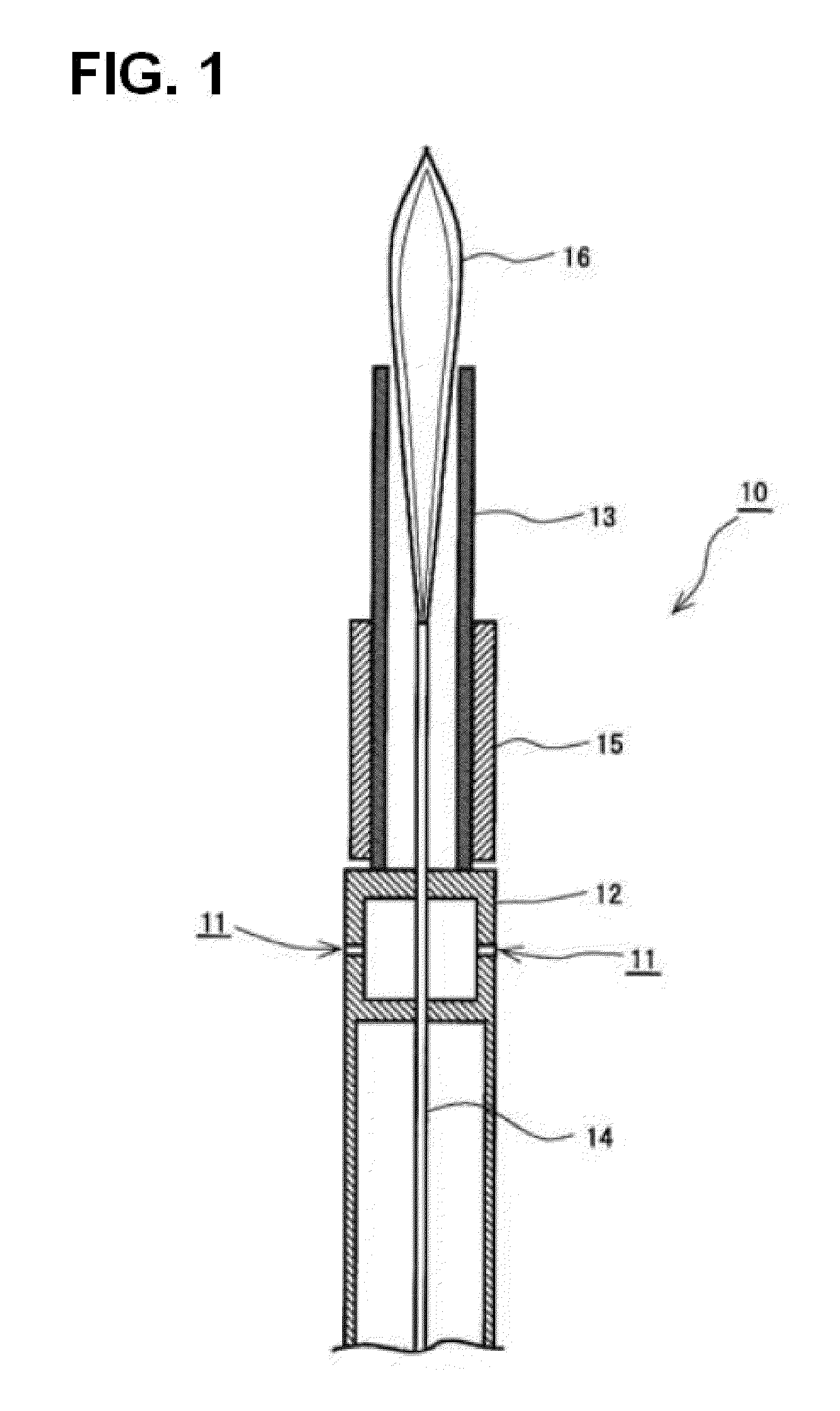
[0034]With the constitution of the present invention shown above, it becomes possible to affix a heat-resistant fuel-activating substance onto the place at comparatively high temperature, such as inside of a combustion device, thus making it possible for the electromagnetic waves radiated from this heat-resistant fuel-activating substance to more directly act on combustion flame. As a result, vibration of methane-based molecules as a kind of active chemical species generated by thermal decomposition of a fuel is activated and the combustion is accelerated, thus leading to a rise in flame temperature and stable combustion flame. As a result, it becomes possible to further decrease the amount of the fuel use.

Problems solved by technology

However, there was no significant effect that enables an improvement in combustion efficiency at the time of combustion.

Method used


Image

  • Heat-resistant fuel-activating substance
  • Heat-resistant fuel-activating substance
  • Heat-resistant fuel-activating substance

Examples


embodiments

(1) Test Results in Boiler

[0079]The above heat-resistant fuel-activating substance was affixed in a specific boiler and the energy saving efficiency was verified. Herein, the “energy saving efficiency” was defined as follows.

[0080]First, a coefficient obtained by dividing the amount of fuel (unit: liter in the case of liquid fuel, m3 in the case of gas fuel) used during the test by the amount of water (unit: m3) used to obtain steam before affixing of the heat-resistant fuel-activating substance was defined as a “fuel use coefficient before affixing” (Eb).

[0081]On the other hand, a coefficient obtained by dividing the amount of fuel used during the test by the amount of water used to obtain steam after affixing of the heat-resistant fuel-activating substance is similarly defined as a “fuel use coefficient after affixing” (Ea).

[0082]Then, an energy saving ratio (η) is defined by the following equation:

η=(Eb−Ea) / Eb×100.

[0083]That is, a ratio (%) of a decrease in amount before and afte...

first embodiment

(1-1) First Embodiment

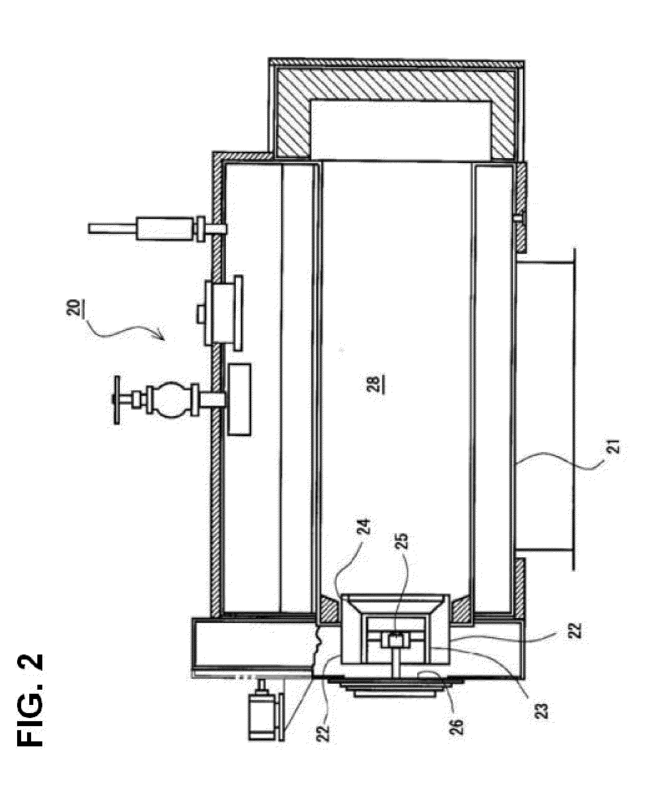
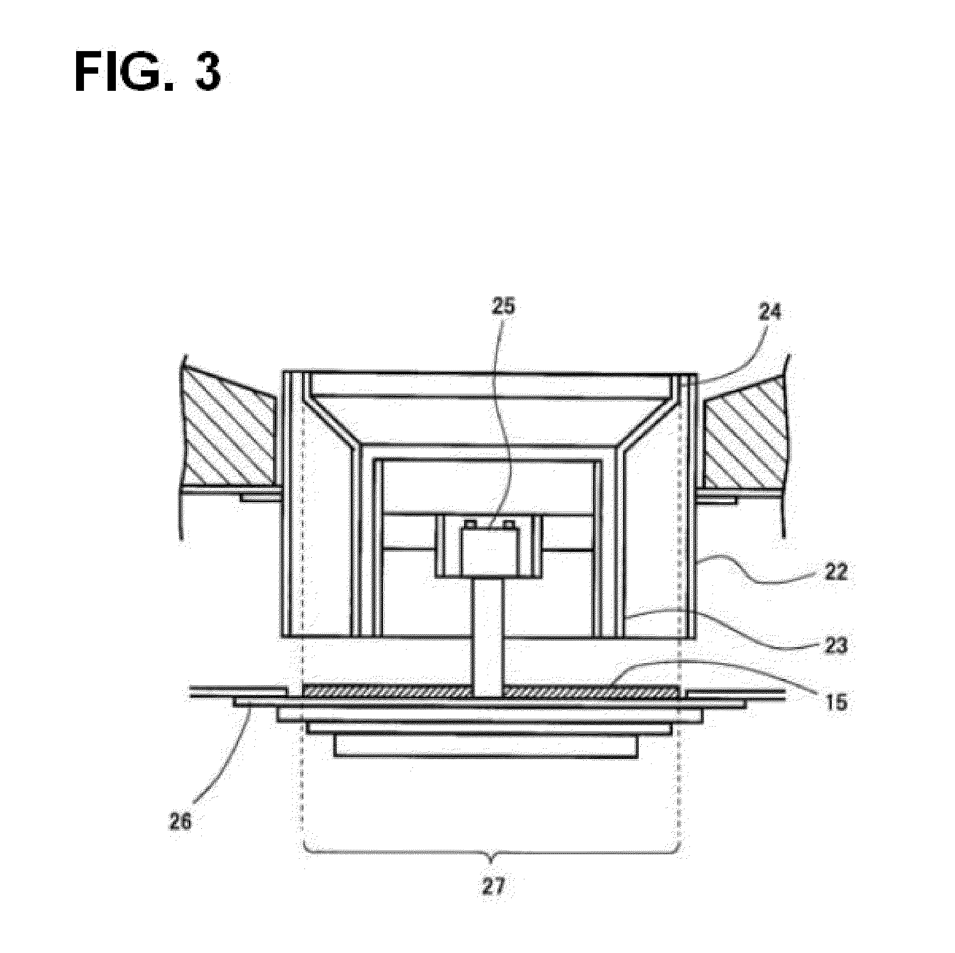
[0085]As the first embodiment, verification was conducted using a flame-tube smoke-tube boiler as a specific boiler. The fuel used in this flame-tube smoke-tube boiler (KMS-16A, IHI PACKAGED BOILER CO., LTD.) was A-heavy oil, the burner used was a gun type burner, the boiler capacity was 8,000 kg / h, and the control method was a proportional control method. FIG. 2 is a schematic view of the flame-tube smoke-tube boiler 20, and FIG. 3 enlarges a gun type burner portion thereof. A combustion device 22 was attached to one end (left end in FIG. 2) of a combustion chamber 28 in a boiler body 21, and a combustion cone 23 enabled a cone maximum diameter portion 24 having the maximum outer diameter to open toward inside the boiler body 21 (rightward in FIG. 2, upward in FIG. 3), and emitted flame from the tip of gun type burner 25 located in almost the shaft center to a center direction of a combustion chamber 28. A flange 26 that fixed the gun type burner 25 was provid...

second embodiment

(1-2) Second Embodiment

[0087]As the second embodiment, verification was conducted using a once-through boiler as a specific boiler. The fuel used in this once-through boiler (STE2001GLM, Nippon Thermoener Co., Ltd.) was LPG, the burner used was a gun type burner, the boiler capacity was 1,667 kg / h, and the control method was a 3-position control method. FIG. 4 is a schematic view of the once-through boiler 30, and FIG. 5 enlarges a gun type burner portion thereof. A combustion device 32 was attached to one end (upper end in FIG. 4) of a combustion chamber 38 in a boiler body 31, and a combustion cone 33 enabled a cone maximum diameter portion 34 having the maximum outer diameter to open toward inside the boiler body 31 (downward in FIG. 4 and FIG. 5), and emitted flame from the tip of gun type burner 35 located in almost the shaft center to a center direction of a combustion chamber 38. A flange 36 that fixed the gun type burner 35 was provided at the rear end of the combustion devi...


PUM

PropertyMeasurementUnit
wavelengthsaaaaaaaaaa
spectral emissivityaaaaaaaaaa
melting pointaaaaaaaaaa

Abstract

A fuel-activating substance comprising a fuel-activating material and having heat resistance imparted thereto. This fuel-activating substance can hence be applied or attached even to parts to be used under such temperature conditions that use with organic resin binders has been impossible, whereby the effect of saving energy in combustion devices is further heightened. The heat-resistant fuel-activating substance is characterized by being obtained by melt-mixing 50-150 wt. % metallic thermal spray material with 100 wt. % fuel-activating material of which the spectral emissivity for electromagnetic waves with wavelengths in the range of 3-20 μm is 0.85 or more and making the mixture capable of thermal spraying. Alternatively, 100 wt. % the fuel-activating material and 50-150 wt. % metallic material having a melting point of 420° C. or lower may be formed into a sheet through melting. Furthermore, a mixture of 100 wt. % the fuel-activating material and 75-150 wt. % inorganic resin having a heat resistance temperature exceeding 300° C. may be formed into a sheet or may be subjected to thermal spraying or applied in a molten state.

Description

TECHNICAL FIELD[0001]The present invention relates to a heat-resistant fuel-activating substance suitable for use in combustion devices such as boilers in which liquid fossil fuels such as heavy oil and kerosene, gas fossil fuels such as LPG and natural gas, and solid fossil fuels such as coal are used as fuels, and enhancing a combustion-activating effect for the combustion therein.BACKGROUND ART[0002]Heretofore, various studies have been conducted for the improvement of thermal efficiency at the time of combustion in combustion devices such as boilers. For that purpose, for example, like the invention described in Patent Document 1, there were some proposals to improve burners.[0003]The inventors of the present invention have proposed that combustion efficiency at the time of combustion is improved by activating methane-based molecules in a thermal decomposition region using electromagnetic waves from a fuel-activating substance. That is, methane-based molecules as a kind of activ...

Claims


Application Information

Patent Timeline
Patent Type & Authority Applications(United States)
IPC IPC(8): C10L1/12
CPCF23C99/001F23C99/00F23K5/08
Inventor TAKAHASHI, SEITAROITO, MASAHIRO
Owner FIRE
Learn More