Reflecting layer-phosphor layer-covered LED, producing method thereof, LED device, and producing method thereof
- Summary
- Abstract
- Description
- Claims
- Application Information
AI Technical Summary
Benefits of technology
Problems solved by technology
Method used
Image
Examples
first embodiment
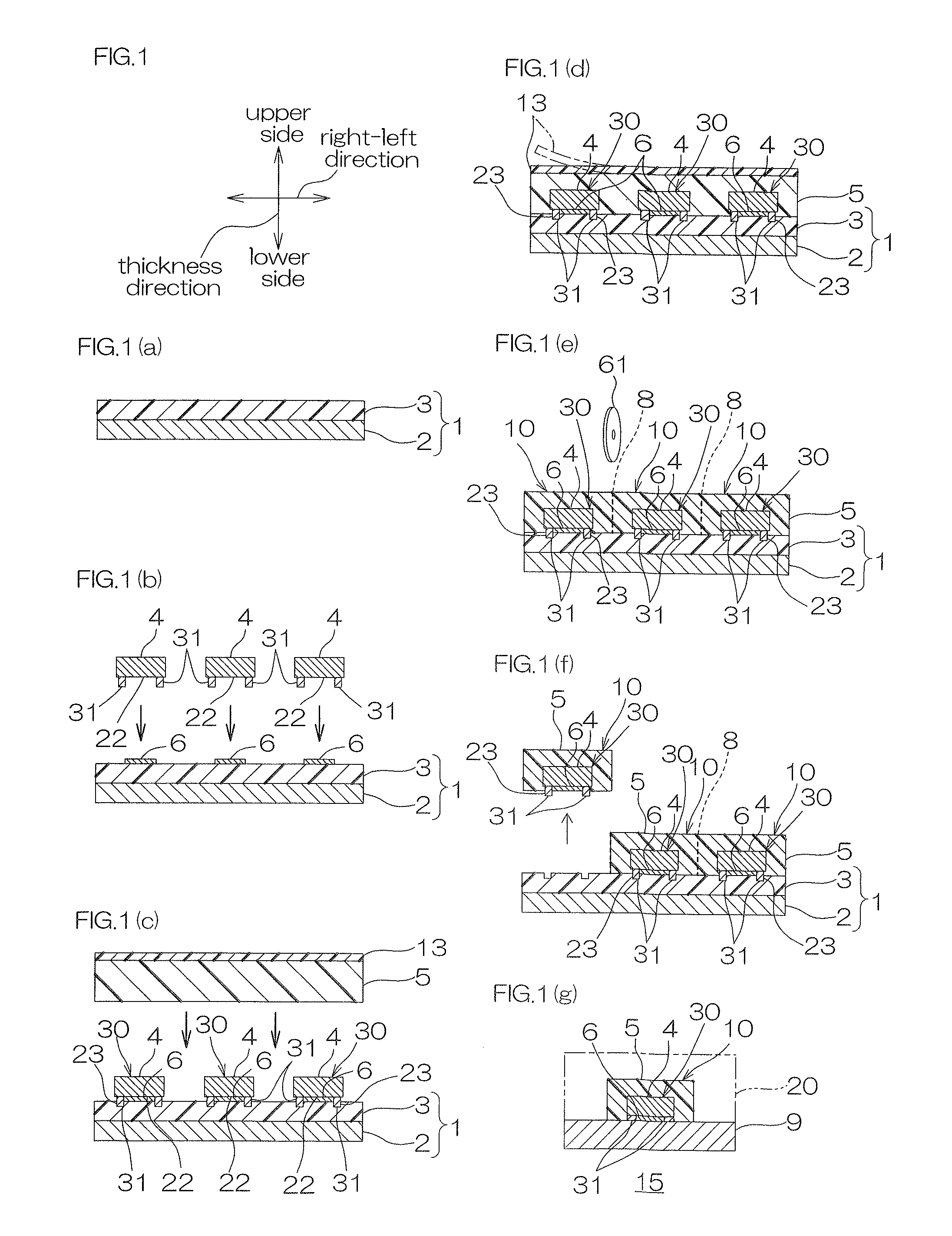
[0191]In FIG. 1, the up-down direction of the paper surface is referred to as an up-down direction (a first direction, a thickness direction); the right-left direction of the paper surface is referred to as a right-left direction (a second direction, a direction perpendicular to the first direction); and the paper thickness direction of the paper is referred to as a front-rear direction (a third direction, a direction perpendicular to the first direction and the second direction). Directions and direction arrows in FIG. 2 and the subsequent figures are in conformity with the above-described directions and the direction arrows in FIG. 1.
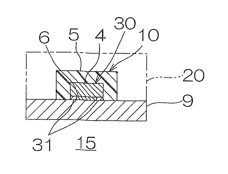
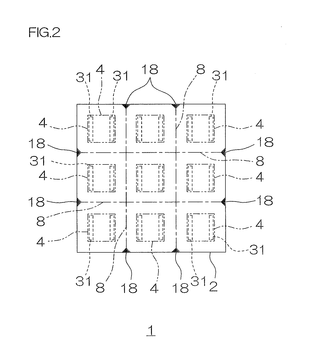
[0192]FIG. 1 shows process drawings for illustrating a first embodiment of a method for producing a reflecting layer-phosphor layer-covered LED of the present invention. FIG. 2 shows a plan view of the support sheet shown in FIG. 1 (a).
[0193]In FIG. 2, a pressure-sensitive adhesive layer 3 to be described later is omitted so as to clearly show the rel...
second embodiment
[0317]FIG. 3 shows process drawings for illustrating a second embodiment of a method for producing a reflecting layer-phosphor layer covered LED of the present invention.
[0318]In FIG. 3, the same reference numerals are provided for members and steps corresponding to each of those in the first embodiment, and their detailed description is omitted.
[0319]In the peeling step (ref: FIG. 1 (f)) in the first embodiment, each of the reflecting layer-phosphor sheet-covered LEDs 10 is peeled from the support board 2 and the pressure-sensitive adhesive layer 3. Alternatively, for example, as shown in FIG. 3 (f), first, the support board 2 is peeled from the pressure-sensitive adhesive layer 3 and thereafter, as shown in FIG. 3 (g), each of the reflecting layer-phosphor sheet-covered LEDs 10 can be peeled from the pressure-sensitive adhesive layer 3 only.
[0320]That is, this method includes the same steps of disposing step (ref: FIGS. 3 (a) and 3 (b)), reflecting layer covering step (ref: FIG. 3...
third embodiment
[0332]FIG. 4 shows process drawings for illustrating a third embodiment of a method for producing a reflecting layer-phosphor layer-covered LED of the present invention.
[0333]In FIG. 4, the same reference numerals are provided for members and steps corresponding to each of those in the first embodiment, and their detailed description is omitted.
[0334]In the peeling steps (ref: FIGS. 1 (f) and 3 (g)) in the first and the second embodiments, each of the reflecting layer-phosphor sheet-covered LEDs 10 is peeled from the support sheet 1 to be then mounted on the board 9 (ref: FIGS. 1 (g) and 3 (h)). Alternatively, for example, as shown in FIGS. 4 (f) and 4 (g), the reflecting layer-phosphor sheet-covered LEDs 10 are sequentially transferred onto a transfer sheet 11 and a stretchable support sheet 24, and thereafter, as shown in FIG. 4 (h), each of the reflecting layer-phosphor sheet-covered LEDs 10 can be peeled from the stretchable support sheet 24.
[0335]That is, this method includes t...
PUM
 Abstract
Description
Claims
Application Information
 - R&D
- Intellectual Property
- Life Sciences
- Materials
- Tech Scout
- Unparalleled Data Quality
- Higher Quality Content
- 60% Fewer Hallucinations
Browse by: Latest US Patents, China's latest patents, Technical Efficacy Thesaurus, Application Domain, Technology Topic, Popular Technical Reports.
© 2025 PatSnap. All rights reserved.Legal|Privacy policy|Modern Slavery Act Transparency Statement|Sitemap|About US| Contact US: help@patsnap.com


