Flat cable and electronic apparatus

Active Publication Date: 2014-01-02
MURATA MFG CO LTD
View PDF0 Cites 13 Cited by
  • Summary
  • Abstract
  • Description
  • Claims
  • Application Information

AI Technical Summary

Benefits of technology

The present invention provides a flat cable that has a bent portion and is not affected by the shape of the bend. This allows for better transmission characteristics.

Problems solved by technology

Recent reductions in the size and thickness of high-frequency apparatuses including mobile communications terminals have led to cases where it is not possible to secure a space for arranging a coaxial cable inside a terminal housing.
However, in this case, a space for realizing a large radius of curvature is required, which presents a problem for a structure that is to be arranged inside a mobile communications terminal for which miniaturization is required.
On the other hand, use of a bent flat cable that is bent at a predetermined angle (for example, 90°) presents the following problem.

Method used


Image

  • Flat cable and electronic apparatus
  • Flat cable and electronic apparatus
  • Flat cable and electronic apparatus

Examples


Embodiment Construction

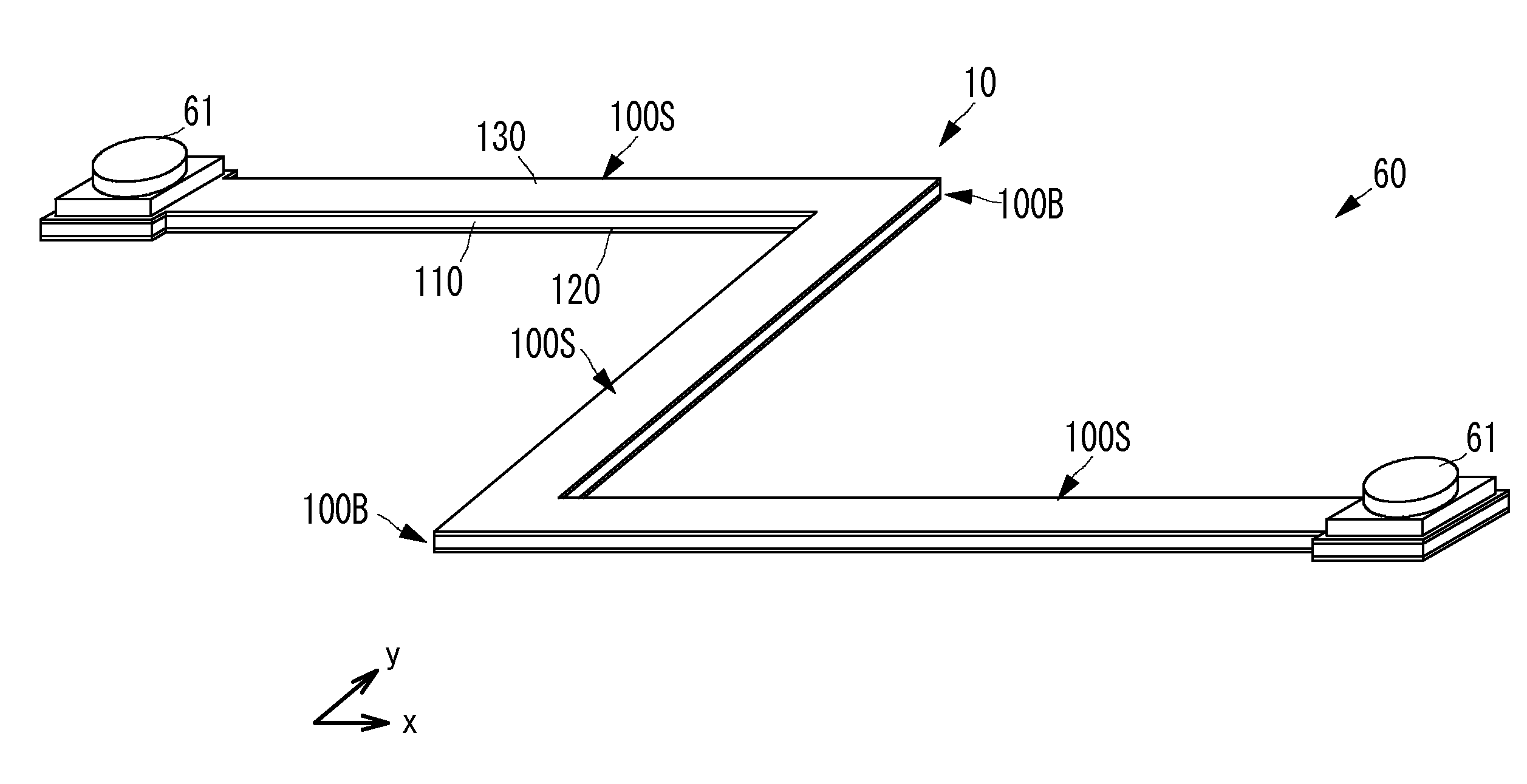
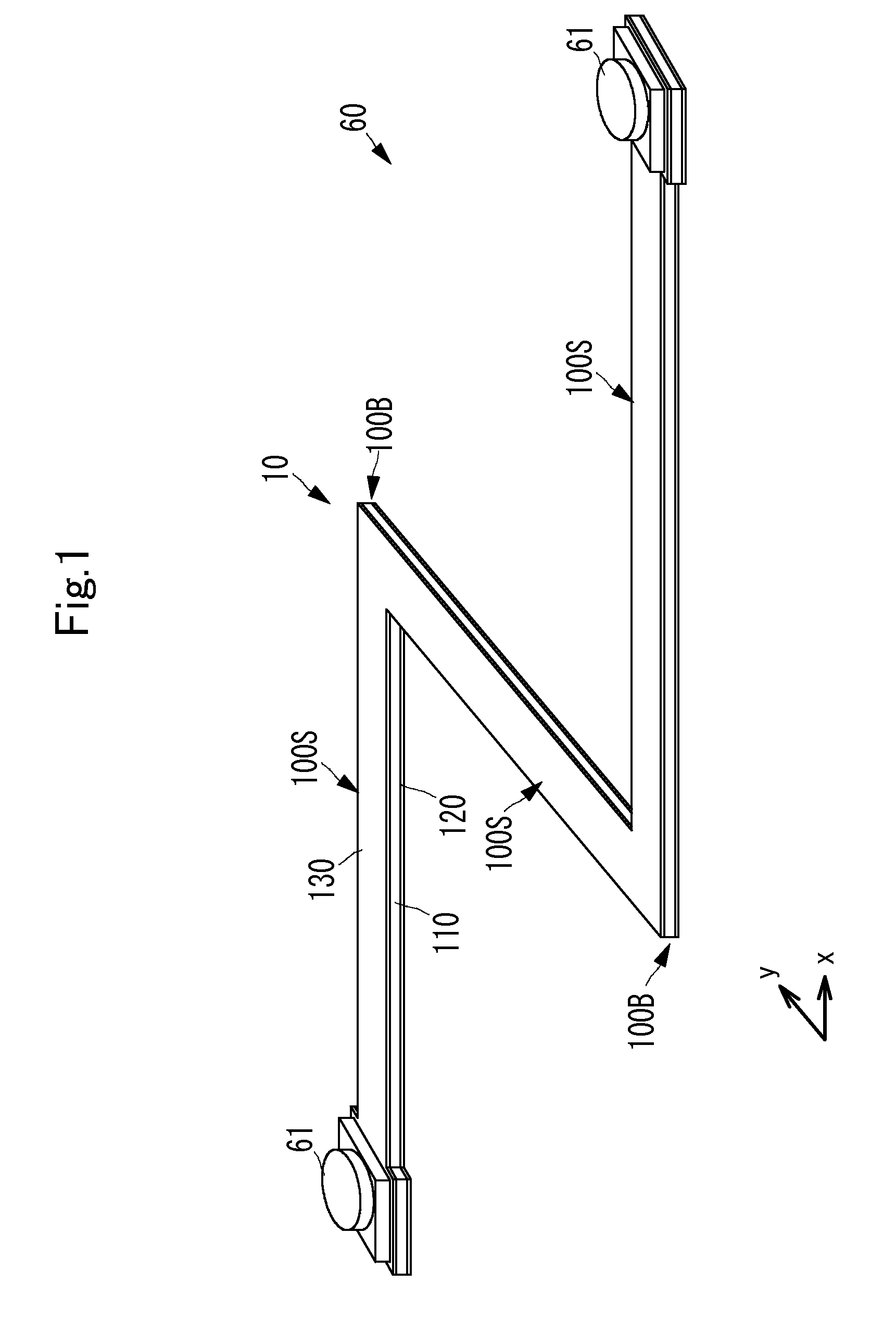
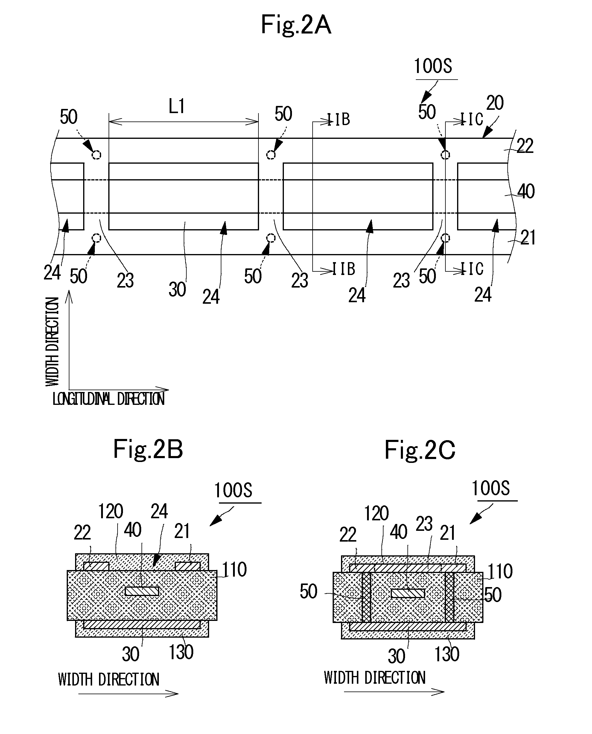
[0048]A flat cable according to a first preferred embodiment of the present invention will be described with reference to the drawings. FIG. 1 is a perspective view of the outward appearance of a flat cable 60 according to the first preferred embodiment of the present invention. FIGS. 2A to 2C illustrate the structure of a straight portion 100S of a transmission line portion 10.

[0049]FIG. 2A is a plan view, as seen from the first principal surface side, of the straight portion 100S in a state in which a dielectric element body 110 is omitted. FIG. 2B is a cross-sectional view taken along a line IIB-IIB of FIG. 2A. FIG. 2C is a cross-sectional view taken along a line IIC-IIC of FIG. 2A. FIG. 3 illustrates the structure of a bent portion 100B of the transmission line portion 10. FIG. 3 is a plan view, as seen from the first principal surface side, of the bent portion 100B in a state in which the dielectric element body 110 is omitted.

[0050]The flat cable 60 includes the transmission l...


PUM


Abstract

A transmission line portion of a flat cable that is bent at a position along the longitudinal direction includes a dielectric element body, a first ground conductor, and a second ground conductor. The dielectric element body includes a signal conductor at the middle position of the thickness direction. The first ground conductor includes elongated conductors and bridge conductors. The elongated conductors are spaced in the width direction of the dielectric element body, and extend in the longitudinal direction. The bridge conductors connect the elongated conductors at spacings along the longitudinal direction. The spacing of bridge conductors across the bending point in a bent portion is smaller than the spacing of adjacent bridge conductors located in a straight portion.

Description

CROSS REFERENCE[0001]This non-provisional application claims priority under 35 U.S.C. §119(a) to Patent Application No. 2012-147866 filed in Japan on Jun. 29, 2012, and Patent Application No. 2013-068343 filed in Japan on Mar. 28, 2013, the entire contents of which are hereby incorporated by reference.BACKGROUND OF THE INVENTION[0002]1. Field of the Invention[0003]The present invention relates to a thin flat cable for transmitting high-frequency signals, and an electronic apparatus including the flat cable.[0004]2. Description of the Related Art[0005]In related art, coaxial cables are typically used as high-frequency lines for transmitting high-frequency signals. A coaxial cable includes a center conductor (signal conductor) that extends in one direction (extends in the direction of signal transmission), and a shield conductor that is provided concentrically along the outer peripheral surface of the center conductor.[0006]Recent reductions in the size and thickness of high-frequency...

Claims


Application Information

Patent Timeline
IPC IPC(8): H01B7/08
CPCH01B7/08H01P3/085H01P3/06
Inventor SHIROKI, KOJISAITO, YOICHIKOYAMA, HIROMASAFUJII, HIROTAKAKATO, NOBORU
Owner MURATA MFG CO LTD
Why Eureka
Try Eureka