

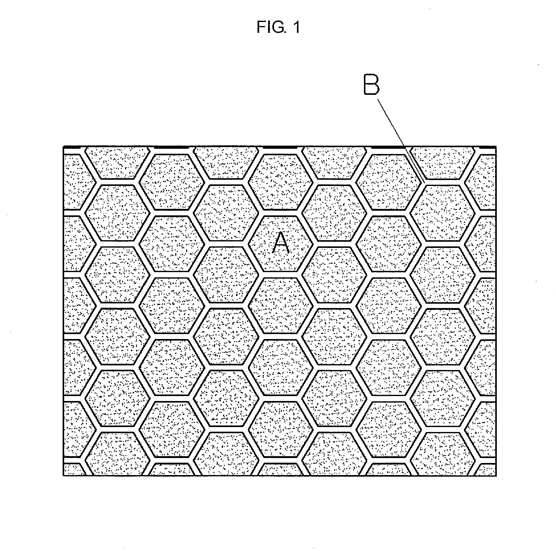
Ceria-based composition including bismuth oxide, ceria-based composite electrolyte powder including bismuth oxide, method for sintering the same and sintered body made thereof
- Summary
- Abstract
- Description
- Claims
- Application Information
AI Technical Summary
Benefits of technology
Problems solved by technology
Method used
Image

Examples
experiment 1
[0089]Each of the powder of Comparative Example and powder of Example 5 (composite electrolyte powder including samarium-doped ceria mixed with bismuth oxide; bismuth oxide content: about 20 wt % based on the total weight of powder) is introduced into a bar-like mold with a size of about 1 cm×about 1 cm×about 3 cm, and subjected to uniaxial pressurized molding, followed by sintering, to provide a sample for measurement of electroconductivity and sintering density.
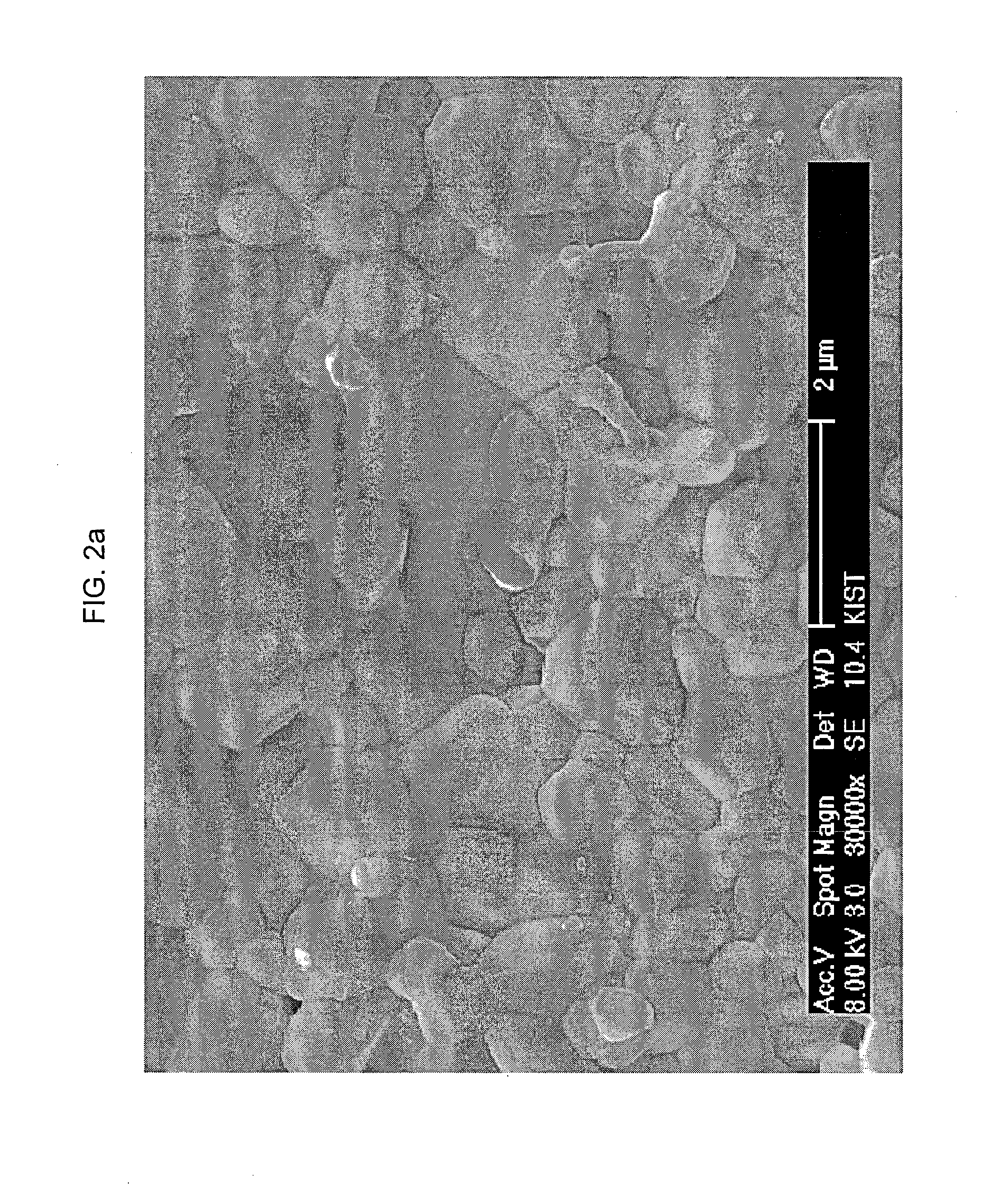
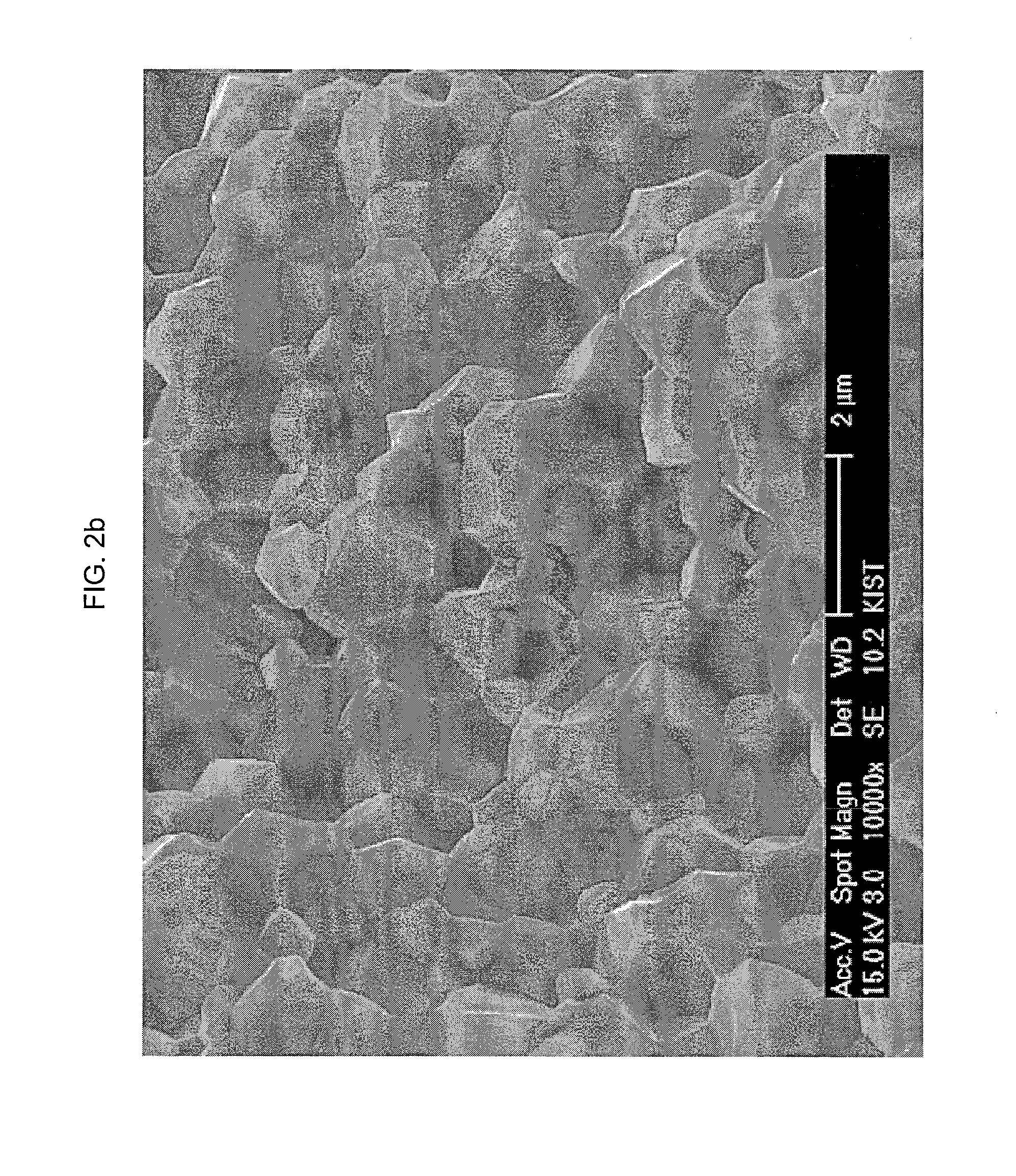
[0090]FIG. 2a and FIG. 2b are scanning electron microscopy (SEM) images of Example 5 (composite powder including samarium-doped ceria mixed with bismuth oxide; bismuth oxide content: about 20 wt % based on the total weight of powder), after it is sintered at 1000° C. for 2 hours, wherein FIG. 2a is the SEM image of the surface and FIG. 2b is the SEM image of a fracture surface. FIG. 3 is an SEM image of the surface of Comparative Example 1 using samarium-doped ceria alone, after it is sintered at about 1500° C. for about 2 ...
experiment 2
[0093]Each of Comparative Example 2 (composite powder including samarium-doped ceria mixed with bismuth oxide; bismuth oxide content: about 1 wt %); Comparative Example 3 (composite powder including samarium-doped ceria mixed with bismuth oxide; bismuth oxide content: about 5 wt %); Example 3 (composite powder including samarium-doped ceria mixed with bismuth oxide; bismuth oxide content: about 10 wt %); Example 4 (composite powder including samarium-doped ceria mixed with bismuth oxide; bismuth oxide content: about 15 wt %); Example 5 (composite powder including samarium-doped ceria mixed with bismuth oxide; bismuth oxide content: about 20 wt %); and Example 6 (composite powder including samarium-doped ceria mixed with bismuth oxide; bismuth oxide content: about 25 wt %) is subjected to ball milling to provide composite powder. Each composite powder is introduced into a bar-like mold with a size of about 1 cm×about 1 cm×about 3 cm, and subjected to uniaxial pressurized molding, fol...
experiment 3
[0096]Electroconductivity is measured for each sample obtained from the powder of Comparative Example 1 and powder of Example 5.
[0097]FIG. 5 is a graph illustrating the results of measurement of electroconductivity of the sintered body obtained by sintering the powder of Comparative Example 1 at about 1500° C. for about 2 hours (shown as ‘▪’ in the graph), and that of the sintered body obtained by sintering the powder of Example 5 (composite powder including samarium-doped ceria mixed with bismuth oxide; bismuth oxide content: about 20 wt % based on the total weight of powder) at about 1000° C. for about 2 hours (shown as ‘▴’ in the graph), wherein X axis represents 1000 / temperature (unit: K−1), and Y axis represents log of conductivity (unit: S / cm)
[0098]As can be seen from FIG. 5, Example 5 provides a higher electroconductivity value as compared to Comparative Example 1 over the whole measurement temperature range (about 600 to about 1000° C.). The powder of Comparative Example 1 s...
PUM
| Property | Measurement | Unit |
|---|---|---|
| Temperature | aaaaa | aaaaa |
| Temperature | aaaaa | aaaaa |
| Temperature | aaaaa | aaaaa |
Abstract
Description
Claims
Application Information