Ultrasound probe

Active Publication Date: 2014-01-02
KONICA MINOLTA INC
View PDF2 Cites 4 Cited by
  • Summary
  • Abstract
  • Description
  • Claims
  • Application Information

AI Technical Summary

Benefits of technology

[0031]Advantageous Effects Of Invention
[0032]The sound probe according to the present disclosure can make the transmission beam

Problems solved by technology

In that case, at a level which is either shallower or deeper than the level at which

Method used


Image

  • Ultrasound probe
  • Ultrasound probe
  • Ultrasound probe

Examples


Example

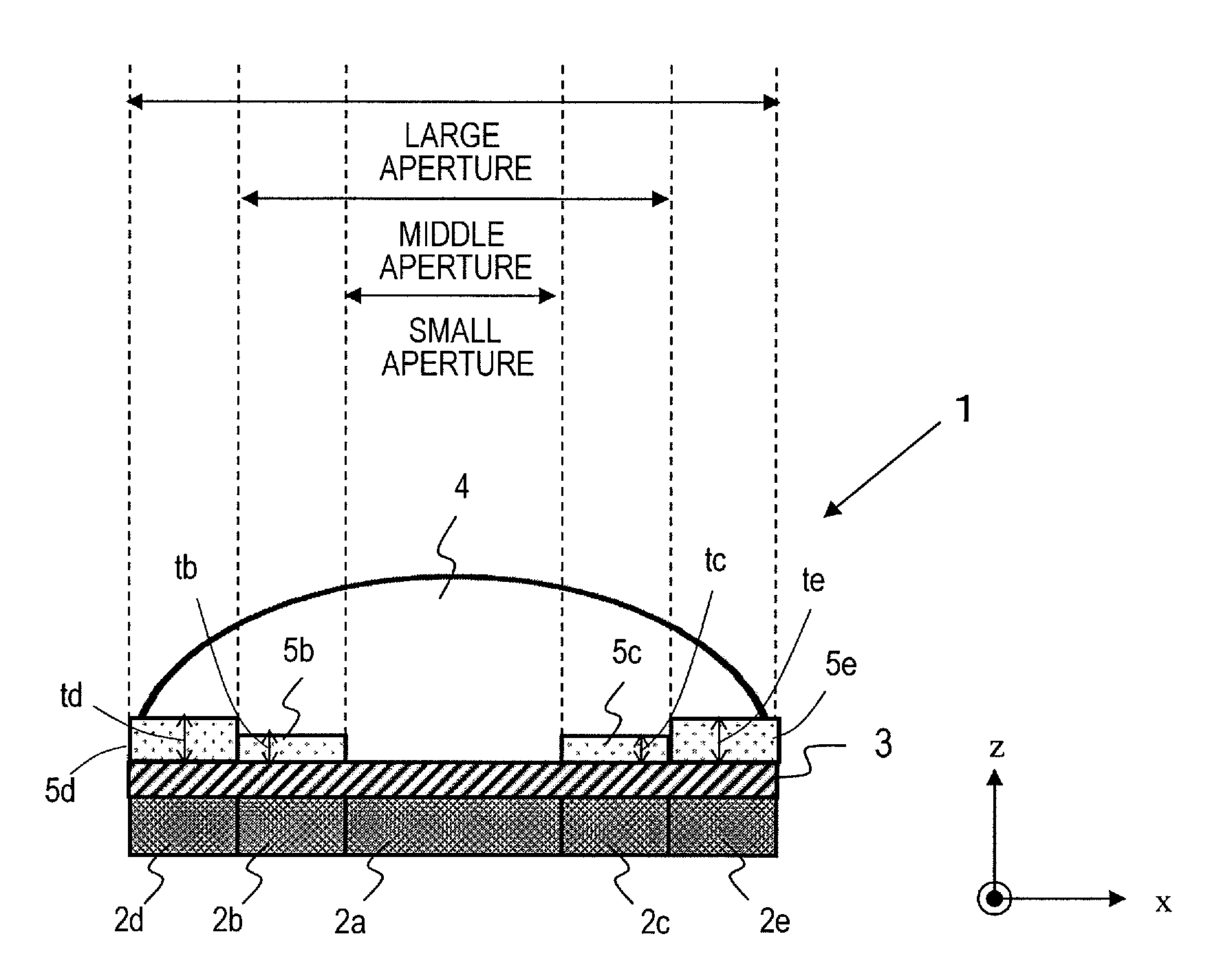
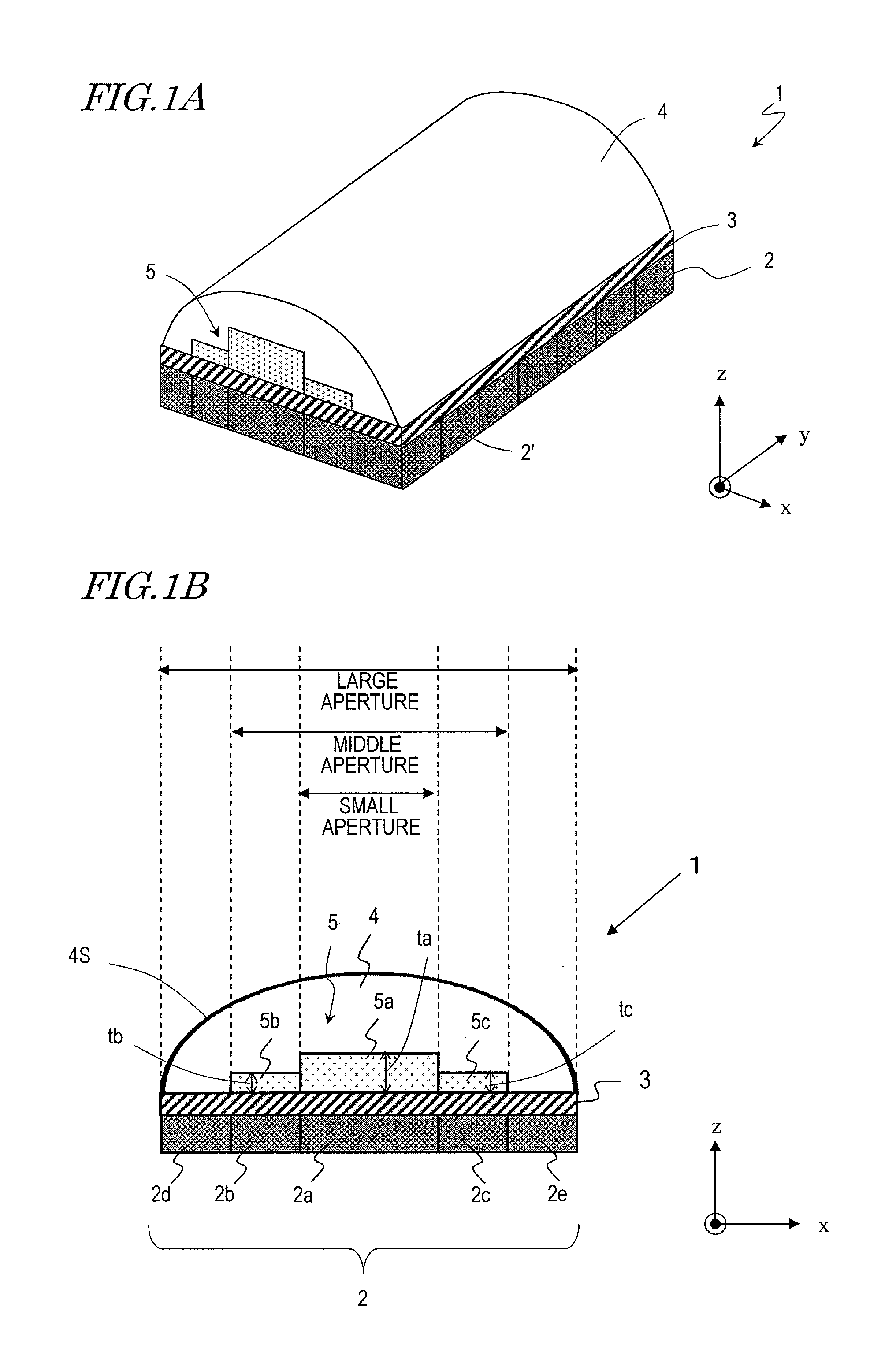
[0052]FIG. 1A is a perspective view illustrating a first embodiment of an sound probe according to the present invention. This sound probe 1 includes an array of transducer elements 2, an acoustic matching layer 3, an acoustic lens 4 and an acoustic adjustment layer 5. As shown in FIG. 1A, the array of transducer elements 2 includes a plurality of transducer elements 2′ which are arranged two-dimensionally in the x direction (first direction) and y direction (second direction). These x- and y-axis directions correspond to the elevation and azimuth directions, respectively. Although not shown in FIG. 1A, each of these transducer elements 2′ is connected to a signal line as in the conventional sound probe. Those signal lines are bundled together into a cable and electrically connected to the body of the ultrasonic diagnostic apparatus (not shown). Each of these transducer elements 2′ is a transducer which makes an interconversion between an electric pulse and an ultrasonic wave and ma...

Example

EMBODIMENT 2

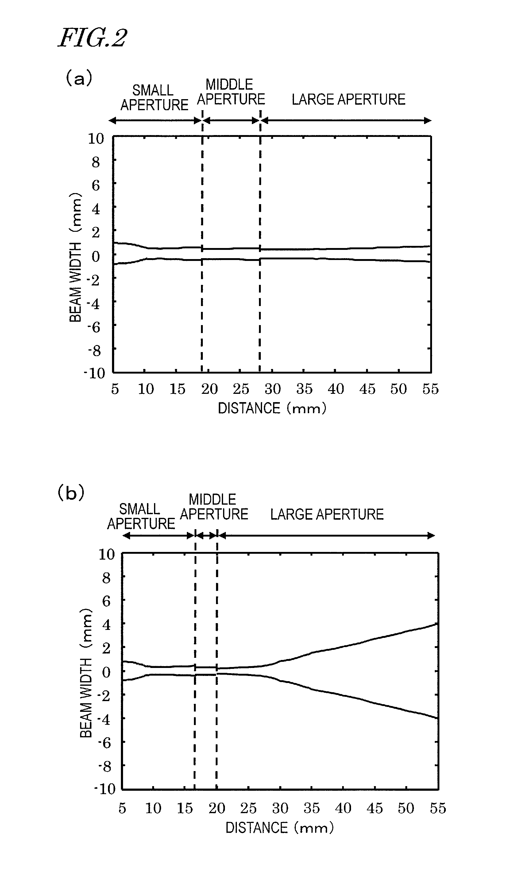
[0085]The first embodiment described above is an sound probe which can narrow the beam width sufficiently even at a relatively deep level in the beam converging direction by using acoustic adjustment layers. A second embodiment to be described below is an sound probe which can further narrow the beam width in a broad range from a relatively shallow level to a relatively deep level.

[0086]FIG. 4 illustrates an x-axis cross section of an sound probe 1 according to this embodiment. This sound probe includes an array of transducer elements, including transducer elements 2a to 2e, an acoustic adjustment layer 5 and an acoustic lens 6. The array of transducer elements 2 and the acoustic adjustment layer 5 have the same structure and are made of the same material as the counterparts of the sound probe 1 of the first embodiment described above.

[0087]The sound probe 1 of the first embodiment described above includes an acoustic lens 4 which has a single curvature and which has a c...

Example

EMBODIMENT 3

[0111]In the first and second embodiments described above, by providing acoustic adjustment layers between transducer elements and an acoustic lens, the phase of ultrasonic waves transmitted from the respective transducer elements (i.e., the amount of time it takes for those ultrasonic waves to reach a certain depth level) is controlled, and the transmitted beam is shaped into a narrower one.

[0112]In this embodiment, transducer elements, each having a surface which is depressed with respect to the outside and transmitting an ultrasonic wave from that concave surface, are used, and the arrival times of pulses of those ultrasonic waves generated from the inner and outer transducer elements or their phase is controlled so that the ultrasonic waves transmitted simultaneously from those transducer elements can reach a certain depth level at as close to the same time as possible.

[0113]As shown in FIG. 9, the sound probe of this embodiment includes transducer elements 7a to 7e,...


PUM


Abstract

An sound probe according to the present disclosure includes: an array of transducer elements in which a plurality of transducer elements are arranged in a first direction and which makes an interconversion between an electric pulse and an ultrasonic wave; an acoustic lens which has a convex surface in a transmission direction of the ultrasonic wave on a cross section that is parallel to the first direction and the transmission direction and which converges the ultrasonic waves transmitted from the plurality of transducer elements; and at least two acoustic adjustment layers which are made of a material that has a different sound velocity from the acoustic lens, which are arranged between at least two of the transducer elements that are arranged in the first direction and the acoustic lens, and of which at least one of the material and a thickness of each of the at least two acoustic adjustment layers in the transmission direction are different from each other.

Description

TECHNICAL FIELD[0001]The present application relates to an sound probe for use in medical ultrasonic diagnostic apparatuses.BACKGROUND ART[0002]An ultrasonic diagnostic apparatus 100 includes an sound probe 101, a cable 102 and the apparatus body 103 as shown in FIG. 11. The sound probe 101 is connected to an electric circuit in the apparatus body 103 through the cable 102 and makes an interconversion on an ultrasonic wave and an electrical signal. The apparatus body 103 performs various kinds of signal processing including transmission processing in which a high-voltage transmission pulse to drive the sound probe 101 is output through the cable 102, reception processing in which a received signal, generated by the sound probe 101 on receiving an ultrasonic wave, is amplified to produce a received beam, brightness modulation of the received signal, and detecting blood flow information from the received signal, and generates an image signal based on the results of these kinds of sign...

Claims


Application Information

Patent Timeline
IPC IPC(8): A61B8/00
CPCA61B8/4477A61B8/4444G10K11/02G10K11/30
Inventor NISHIGAKI, MORIO
Owner KONICA MINOLTA INC
Why Eureka
Try Eureka