Face Protector Lens Assembly and Method of Use

a technology of face protectors and lens assemblies, which is applied in the field of face protector lens assemblies, can solve the problems of flammable objects in the welding area, easy damage, and damage to the skin, and achieve the effects of reducing the risk of damage, reducing the safety of use, and reducing the risk of injury

Active Publication Date: 2014-01-09
MENTA PATENT PARTNERS LLC +1
View PDF11 Cites 48 Cited by
  • Summary
  • Abstract
  • Description
  • Claims
  • Application Information

AI Technical Summary

Benefits of technology

[0010]In one embodiment, the ADF retainer lens has a window opening aligned with the ADF lens, and four “scrap book frame” type corners formed integrally in its front face around the window opening for engagement with corners of an outer protective lens or cover. This makes it easier for users to replace the outer protective lens or cover without needing to disassemble the cover from the inside of the welding helmet or face protector in which the lens assembly is mounted. Since the outer protective lens or cover is exposed to a welding environment in which scratching and damage is common, the cover sometimes needs to be replaced multiple times in one day of work. By making the outer protective lens replaceable quickly and easily from the front of the helmet or face protector simply by releasing it from the externally accessible scrap book frame corners, without requiring any disassembly, workers can be much more productive.
[0011]In one embodiment, the second lens may be releasably secured behind the first lens by a retainer assembly having a rear retainer frame and a gasket between the retainer frame and second lens, and the rear retainer frame is secured to the first lens by one ore more releasable fasteners. This allows the second lens to be replaced by second lenses of different properties, while the flexible gasket allows second lenses of different depths to be secured in the assembly.

Problems solved by technology

Both conditions are caused by unprotected exposure to the highly-concentrated UV rays emitted by the welding arc (which can also damage uncovered skin, similar to a sunburn).
Either type, however, is susceptible to damages such as cracks that can compromise the protection from ultraviolet rays.
The hot metal sparks generated by the arc can ignite flammable objects in the welding area.
Because the welding helmets include a small window directly in front of the welder's eyes and have obstructed peripheral vision or even no peripheral vision, a welder may not recognize that the hot metal sparks generated a fire in the area (e.g., to the sides) of the welder.
The obstructed peripheral vision also prevents the welder from clearly seeing the future direction of their welding line, and they also may not see potential dangers such as people walking up to them from the side or objects moving or falling into their path.

Method used


Image

  • Face Protector Lens Assembly and Method of Use
  • Face Protector Lens Assembly and Method of Use
  • Face Protector Lens Assembly and Method of Use

Examples


Embodiment Construction

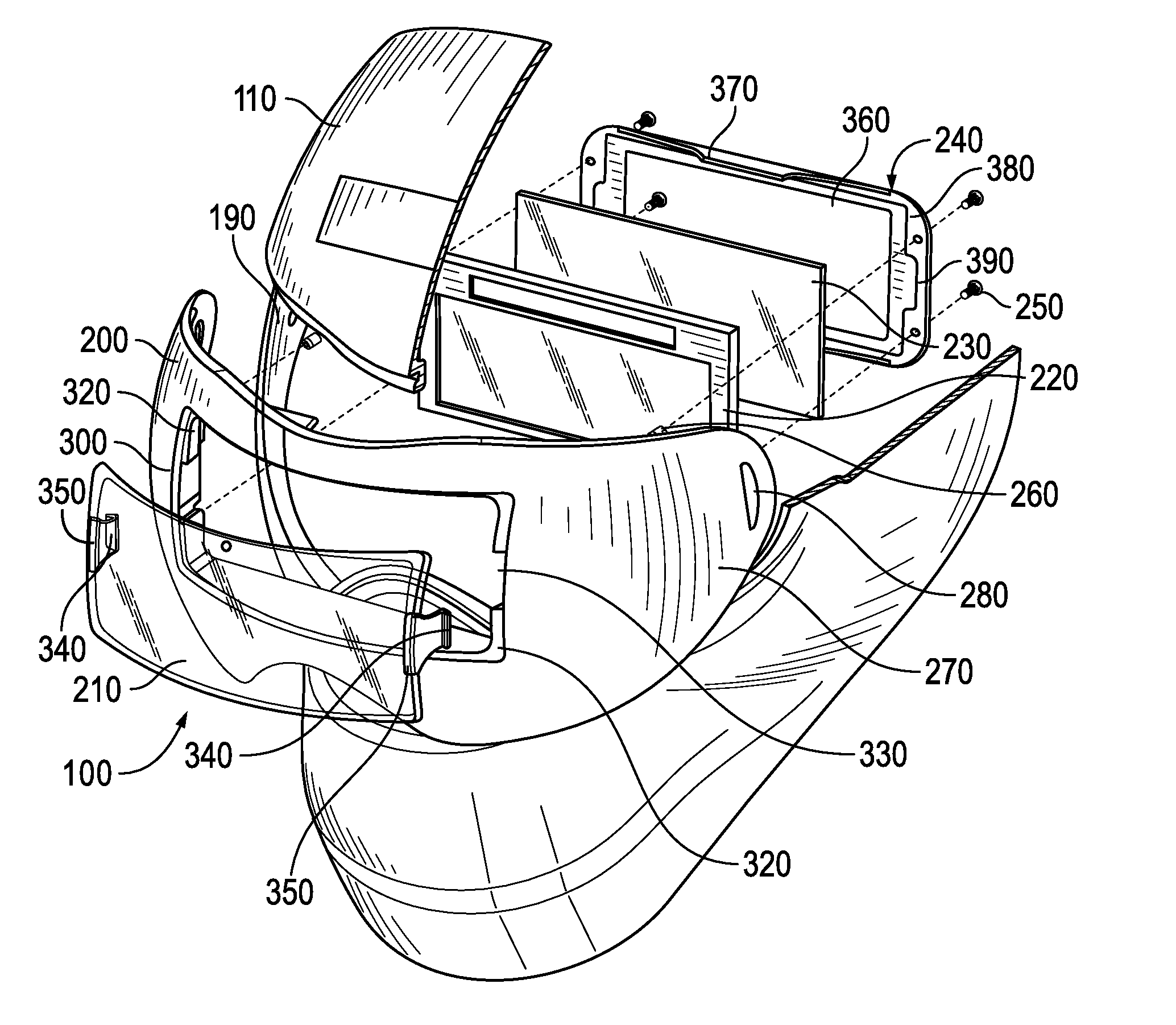
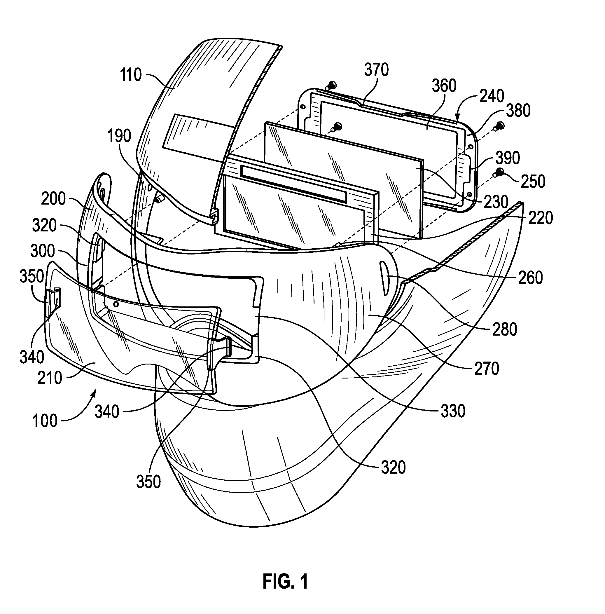
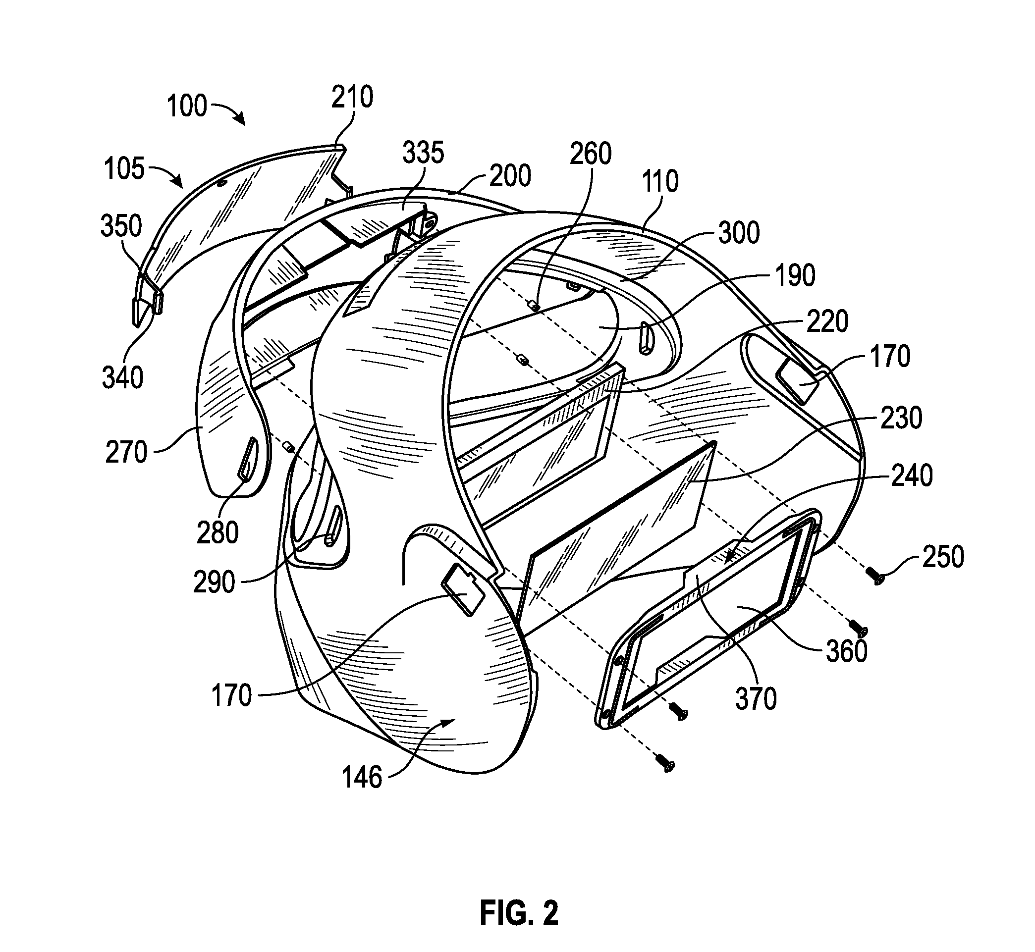
[0039]Certain embodiments as disclosed herein provide for a face protector having a face plate with a front opening which extends across the eye region of a wearer and rearwardly around the sides of the face towards the ears, and a lens-in-a-lens assembly secured in the front opening.

[0040]After reading this description it will become apparent to one skilled in the art how to implement the invention in various alternative embodiments and alternative applications. However, although various embodiments of the present invention will be described herein, it is understood that these embodiments are presented by way of example only, and not limitation. As such, this detailed description of various alternative embodiments should not be construed to limit the scope or breadth of the present invention.

[0041]With reference to FIGS. 1-9, a first embodiment of a lens-in-a-lens assembly (“lens assembly”) 100 of a face protector 105 will be described. In an exemplary embodiment, the face protecto...


PUM


Abstract

A retainer lens of shape and dimensions configured to be releasably secured in the front opening of a face plate or helmet has a window opening configured for positioning in front of the eyes of a wearer of the face plate or helmet. An outer protective cover is configured to be secured over the window opening by means of scrap-book like frame corners located on the front surface of the retainer lens and spaced outwardly from respective corners of the window opening. The corners of the outer protective cover are releasably engaged with respective frame corners, so that the cover can be removed from the outside of the face plate as needed for replacement with a new outer protective cover, simply by removing the corners of the current outer protective cover from the respective frame corners, and then engaging a new outer protective cover into the frame corners.

Description

CROSS-REFERENCE TO RELATED APPLICATIONS[0001]The present application is a Continuation In Part of U.S. patent application Ser. No. 13 / 893,192 filed on May 13, 2013, which is a Continuation of U.S. patent application Ser. No. 13 / 081,699 filed Apr. 7, 2011, now U.S. Pat. No. 8,438,663, which is a Continuation In Part of patent application Ser. No. 12 / 950,846 filed on Nov. 19, 2010, now U.S. Pat. No. 8,438,662, which claims the benefit of U.S. provisional pat. App. Ser. No. 61 / 263,765, filed Nov. 23, 2009, and the contents of each of the aforementioned applications are incorporated herein by reference in their entirety.BACKGROUND[0002]1. Field of the Invention[0003]The present invention relates, in general, to lenses of face protectors, and, in particular, to lenses of welding masks or helmets.[0004]2. Related Art[0005]Welding helmets or masks are headgear used when performing certain types of welding to protect the eyes, face and neck from flash burn, ultraviolet light, sparks and hea...

Claims


Application Information

Patent Timeline
Patent Type & Authority Applications(United States)
IPC IPC(8): A61F9/06
CPCA61F9/06A61F9/064B23K9/322F16P1/06
Inventor WRIGHT, JERRY DEAN
Owner MENTA PATENT PARTNERS LLC
Why Eureka
Try Eureka