Retaining collar for a gas turbine combustion liner

a technology of combustion liner and retaining collar, which is applied in the direction of machines/engines, burner ignition devices, lighting and heating apparatus, etc., can solve the problems of excessive wear and fracturing of floating collars, and require premature replacement of peripheral devices, so as to minimize any interaction

Active Publication Date: 2014-01-09
ANSALDO ENERGIA SWITZERLAND AG
View PDF7 Cites 20 Cited by
  • Summary
  • Abstract
  • Description
  • Claims
  • Application Information

AI Technical Summary

Benefits of technology

[0008]In yet another embodiment of the present invention, a collar cap for retaining a floating collar of a combustion liner is provided. The collar cap includes a series of inner diameters and planar surfaces with an angled surface connecting an upper planar surface to an ou

Problems solved by technology

Furthermore, such contact also causes excessive wear and fracturing of the fl

Method used


Image

  • Retaining collar for a gas turbine combustion liner
  • Retaining collar for a gas turbine combustion liner
  • Retaining collar for a gas turbine combustion liner

Examples


Embodiment Construction

[0020]The subject matter of the present invention is described with specificity herein to meet statutory requirements. However, the description itself is not intended to limit the scope of this patent. Rather, the inventors have contemplated that the claimed subject matter might also be embodied in other ways, to include different components, combinations of components, steps, or combinations of steps similar to the ones described in this document, in conjunction with other present or future technologies.

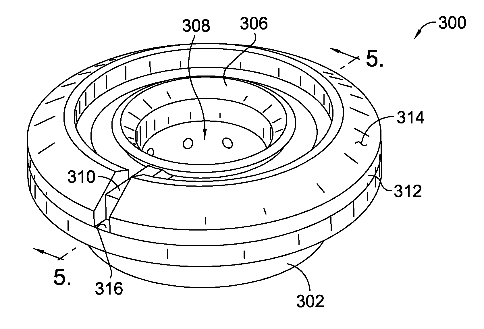
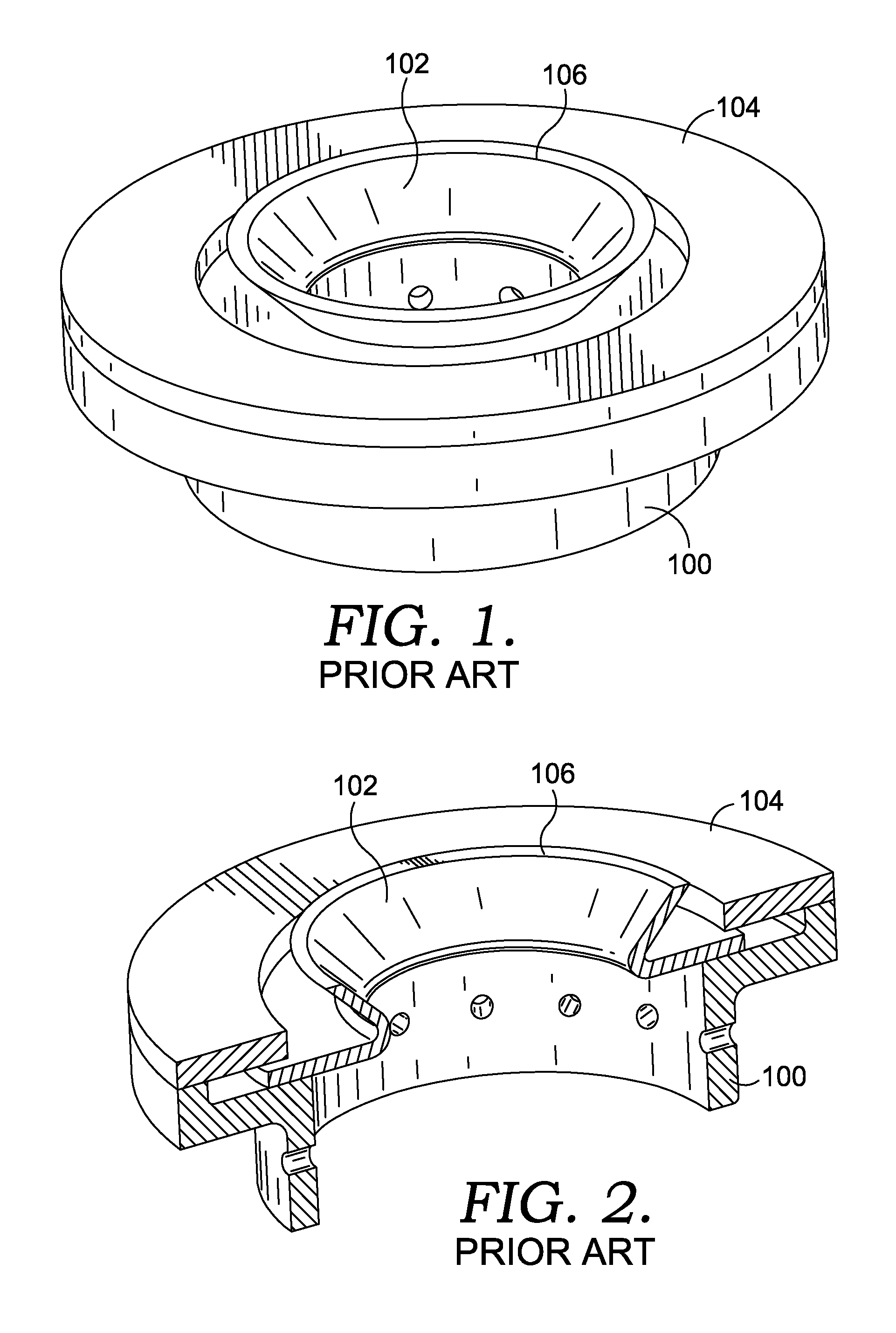
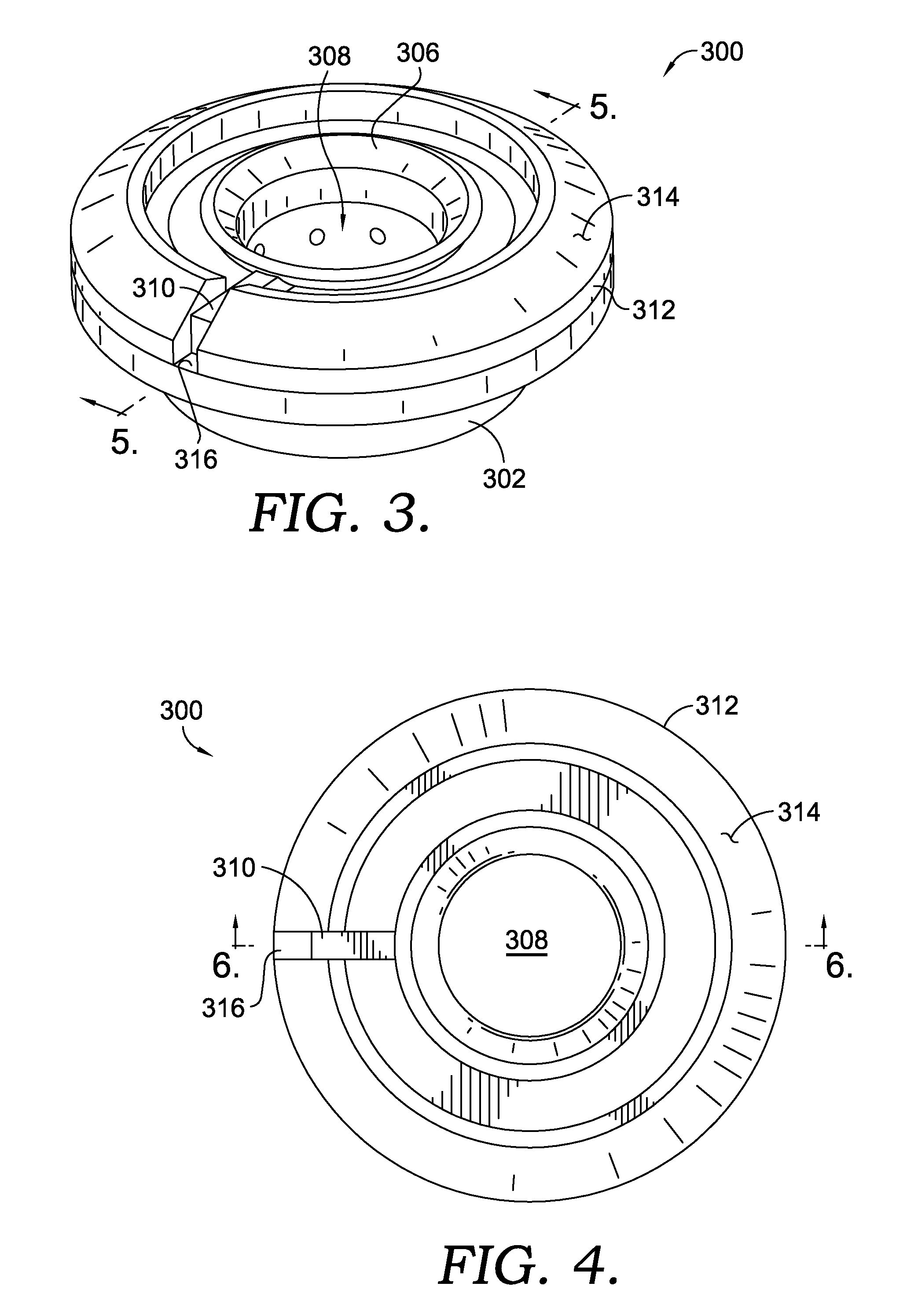
[0021]The present invention is directed generally towards a retaining collar assembly for use in a combustion liner of a gas turbine engine. Referring initially to FIGS. 3-5, a retaining collar assembly 300 for a gas turbine combustor is disclosed. The retaining collar assembly 300 comprises a generally cylindrical liner boss 302 that extends generally radially outward from a combustion liner 350 and has a planar surface 304, as shown in FIGS. 5 and 6. The retaining collar assembly ...


PUM


Abstract

A gas turbine combustion liner having a novel and improved system for receiving a peripheral device through a floating collar is disclosed. The retaining collar assembly provides planar movement for receiving the peripheral device while preventing the floating collar from rotational movement through an anti-rotation tab on the collar and a collar cap, resulting in reduced wear to the peripheral device. The collar cap can include different configurations for reducing any vibratory effects caused by an oncoming airflow directly contacting the floating collar.

Description

CROSS-REFERENCE TO RELATED APPLICATIONS[0001]None.TECHNICAL FIELD[0002]The present invention generally relates to a retaining collar of a combustion liner capable of receiving a peripheral device such as a flame detector, igniter, or other instrumentation for a gas turbine combustion system.BACKGROUND OF THE INVENTION[0003]In a typical gas turbine engine used in a powerplant application, a plurality of combustors is arranged in an annular array about a centerline of the engine. The combustors receive pressurized air from the engine's compressor, add fuel to create a fuel / air mixture, and ignite the mixture to produce hot combustion gases. The hot combustion gases exit the combustors and enter a turbine, where the expanding gases are utilized to drive a turbine, which is in turn coupled through a shaft to the compressor. The engine shaft is also coupled to a shaft that drives a generator for generating electricity.[0004]The combustors typically include at least a pressurized case and...

Claims


Application Information

Patent Timeline
IPC IPC(8): F23R3/02
CPCF23R3/283F02C7/266F23D2207/00F23R3/02F23R3/06F23R3/60F23R2900/00005F23R2900/00012F23R2900/03042F23R2900/03043
Inventor RICHARDSON, BRIAN K.CIRES, ALFREDOHENRIQUEZ, JOHNSULLIVAN, DANIEL J.POWELL, KEVIN B.
Owner ANSALDO ENERGIA SWITZERLAND AG
Why Eureka
Try Eureka