Robotic hand with conformal finger

Active Publication Date: 2014-01-09
RE2
View PDF7 Cites 44 Cited by
  • Summary
  • Abstract
  • Description
  • Claims
  • Application Information

AI Technical Summary

Benefits of technology

[0018]The ramp angles are adjusted to control sensitivity, and a shallow ramp angle will increase sensitivity. The gear reducer provides dwell points for positi

Problems solved by technology

These systems are deployed in uncontrolled environments.
In the past, movement of fingers is accomplished through very complex mechanical linkages and has often required

Method used


Image

  • Robotic hand with conformal finger
  • Robotic hand with conformal finger
  • Robotic hand with conformal finger

Examples


Embodiment Construction

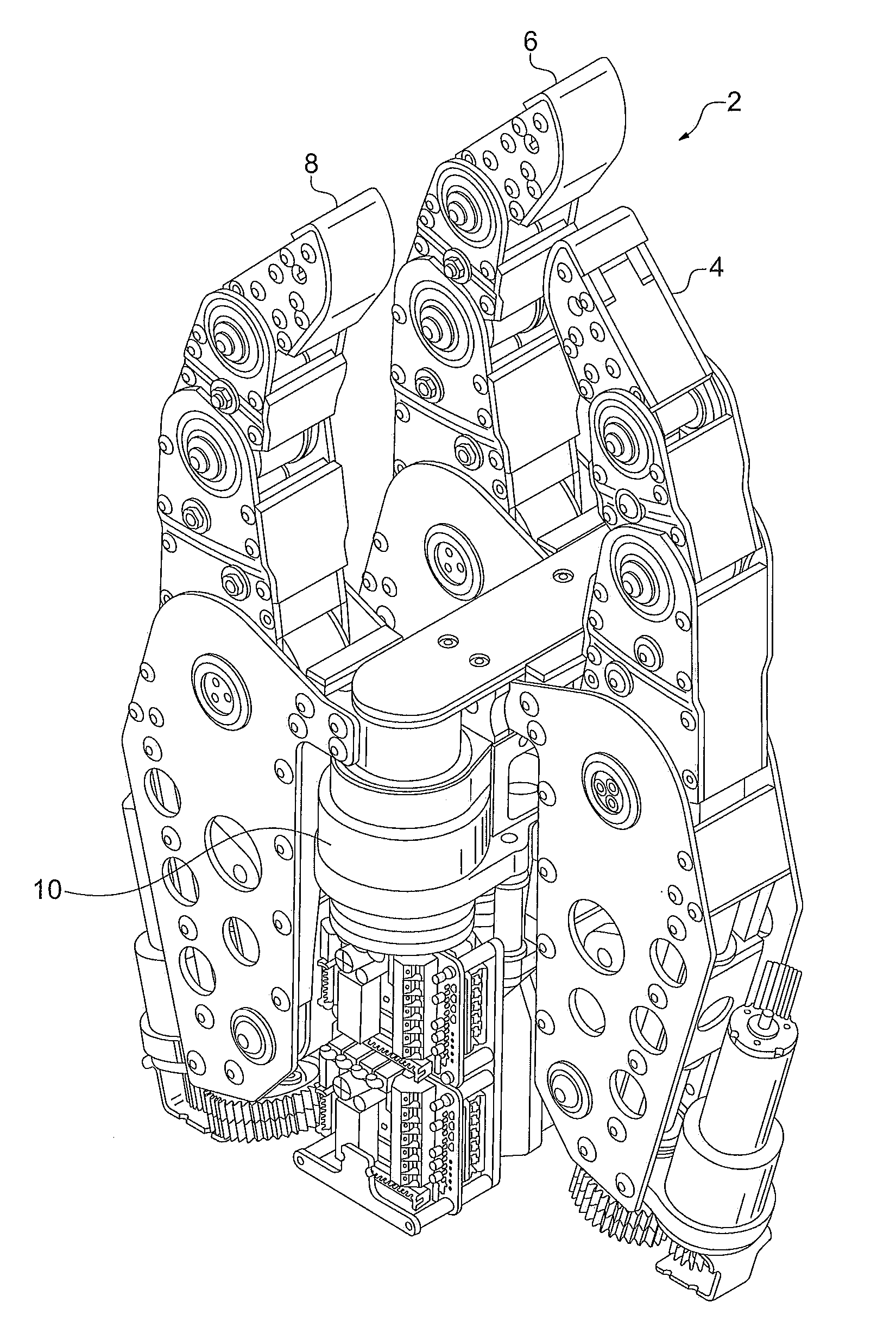
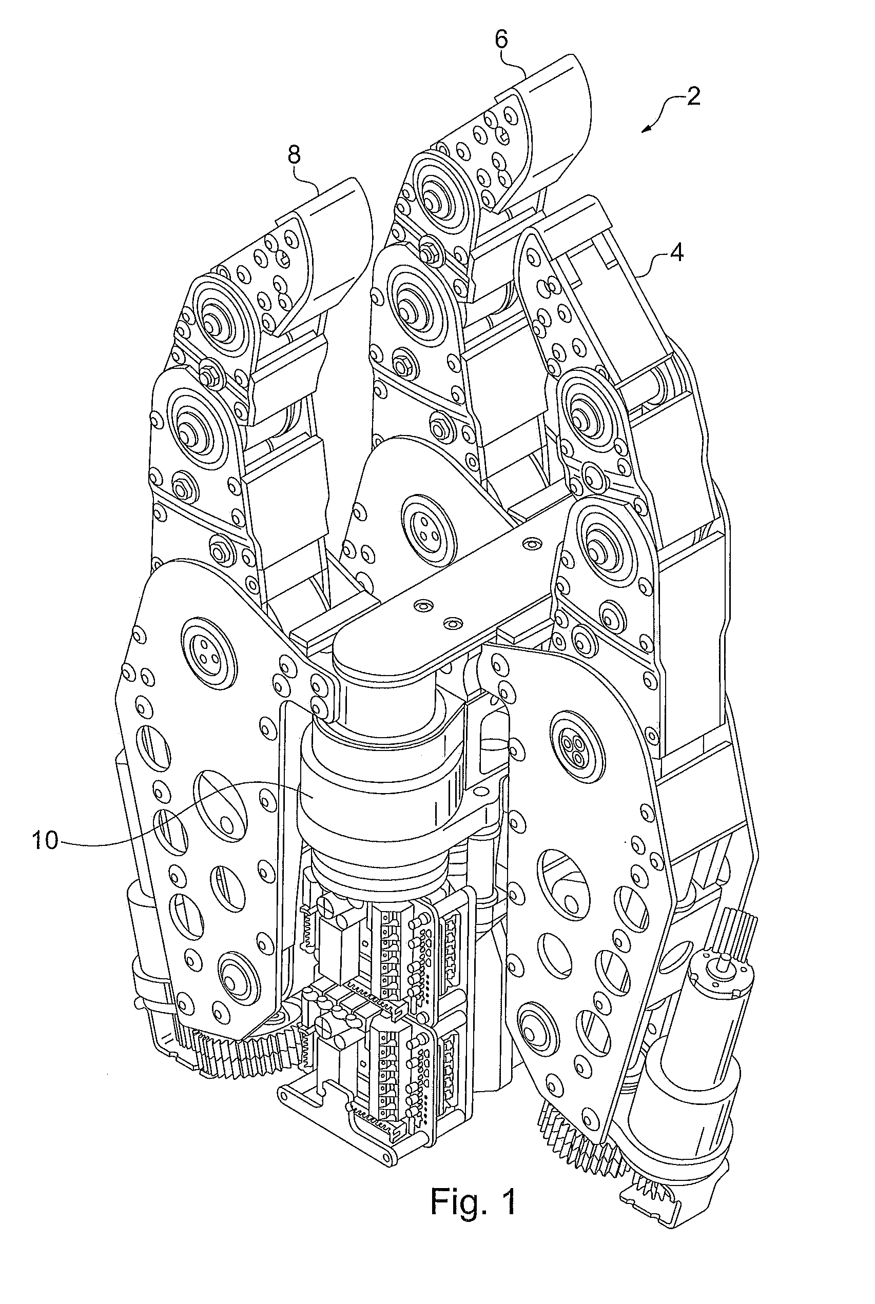
[0044]With reference to FIG. 1, a robotic hand assembly 2 is shown, having conformal movement to provide both grasping and pinching of objects. The robotic hand assembly 2 includes a stationary finger 4 and two adjustable fingers 6 and 8. The fingers 4, 6, and 8 are lightweight and each driven by a single motor. The fingers are conforming and have a predictive behavior along with static equilibrium which provides adaptability to unique situations and environments. In addition, the hand assembly can have a palm actuator 10. The fingers 4, 6, and 8 are conformal fingers which can be used to grasp objects. The hand assembly provides the ability for the user to reset the fingers by operating the hand assembly to have the fingers fully open. When grasping an object, as shown in FIG. 2, such as a large artillery shell, the fingers conform to the object with a uniformity throughout the hand assembly 2 and provide distributed pressure throughout the object. As the fingers apply pressure to ...


PUM


Abstract

A robotic finger assembly can include a base for mounting the finger to a robotic hand, with the base having a motor, and at least three links. The links of the robotic hand are connected to each other and to the base by a series of joints. A joint shaft and a pivot shaft, where the pivot shaft can freely move within its respective joint shaft, is connected to a preceding link. The motor is activated for opening or closing the finger. The finger closes on an object with a distributed force across the links. Grasping also can mean engaging an object like a human hand, by closing the first finger link until it engages the object, then closing the second finger link until it engages the object, then closing the third link until it engages the object. A robotic hand assembly is also disclosed.

Description

BACKGROUND OF THE INVENTION[0001]1. Field of the Invention[0002]The present invention relates to a robotic finger which can be used on a robotic hand.[0003]2. Description of Related Art[0004]Military and law enforcement groups are increasingly relying on UGVs to perform life-threatening tasks ranging from under car inspection to EOD. As small UGVs, such as Omni-Directional Inspection Systems (ODIS), Talon and Packbot have gained acceptance, the variety of tasks they have been required to perform has increased.[0005]These systems are deployed in uncontrolled environments. They must have a robust design to survive the normal working environment they will encounter, both during deployment on the mobile robot and when the manipulator and tools are being stored or transported. The mechanical connection must be resilient to minor variations in tolerances of mating components, such as might occur when a tool is dropped or bumps against another tool in the toolbox, or such as might be cause...

Claims


Application Information

Patent Timeline
IPC IPC(8): B25J15/00
CPCB25J15/0009Y10S901/39Y10S901/38Y10T74/20317
Inventor DELOUIS, MARK J.
Owner RE2
Why Eureka
Try Eureka