Forward-pressed finger rest for slide-action stock

a slide-action stock and forward-pressed technology, which is applied in the field of manual reciprocation slide-action stock for semi-automatic firearms, can solve the problems of many safety and accuracy issues of belt loop method, operator's skin burns or possibly pinches, and operator's sleeve or skin burns, etc., to achieve the effect of increasing the firing rate of a semi-automatic firearm without compromising the safety of the user or the accuracy of the firearm, and not pron

Inactive Publication Date: 2014-01-09
SLIDE FIRE SOLUTIONS
View PDF28 Cites 16 Cited by
  • Summary
  • Abstract
  • Description
  • Claims
  • Application Information

AI Technical Summary

Benefits of technology

[0012]This invention fulfills many needs in the sporting arms field, including enabling shooters to practice new and interesting ways to shoot firearms in a legal and safe manner, increasing the firing rate of a semi-automatic firearm without compromising the safety of the user or the accuracy of the firearm, providing generally universal functional without respect to ammunition type, and in compliance with federal firearms regulations. This present invention represents an improved interface device disposed operatively between the firing unit of a firearm and the handle portion of a firearm that is durable, sturdy, and not prone to binding in use.

Problems solved by technology

Although able to achieve a high rate of firing, the belt loop method has many safety and accuracy issues.
This could lead to skin burns or possibly pinch the operator's sleeve or skin in the action.
Another issue with the belt loop method arises because the operator cannot have a firm grip on the firearm.
Because of this unnatural and unbalanced firing grip, the firearm is very difficult to aim and control during the belt loop method.
However, the same safety and accuracy issues of the belt loop method apply to these devices because the firearm cannot be held securely with the trigger hand or the stock of the firearm.

Method used


Image

  • Forward-pressed finger rest for slide-action stock
  • Forward-pressed finger rest for slide-action stock
  • Forward-pressed finger rest for slide-action stock

Examples


Embodiment Construction

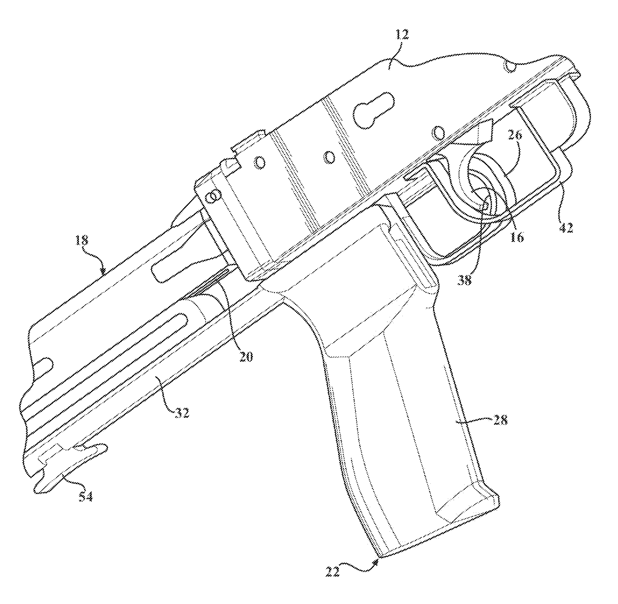
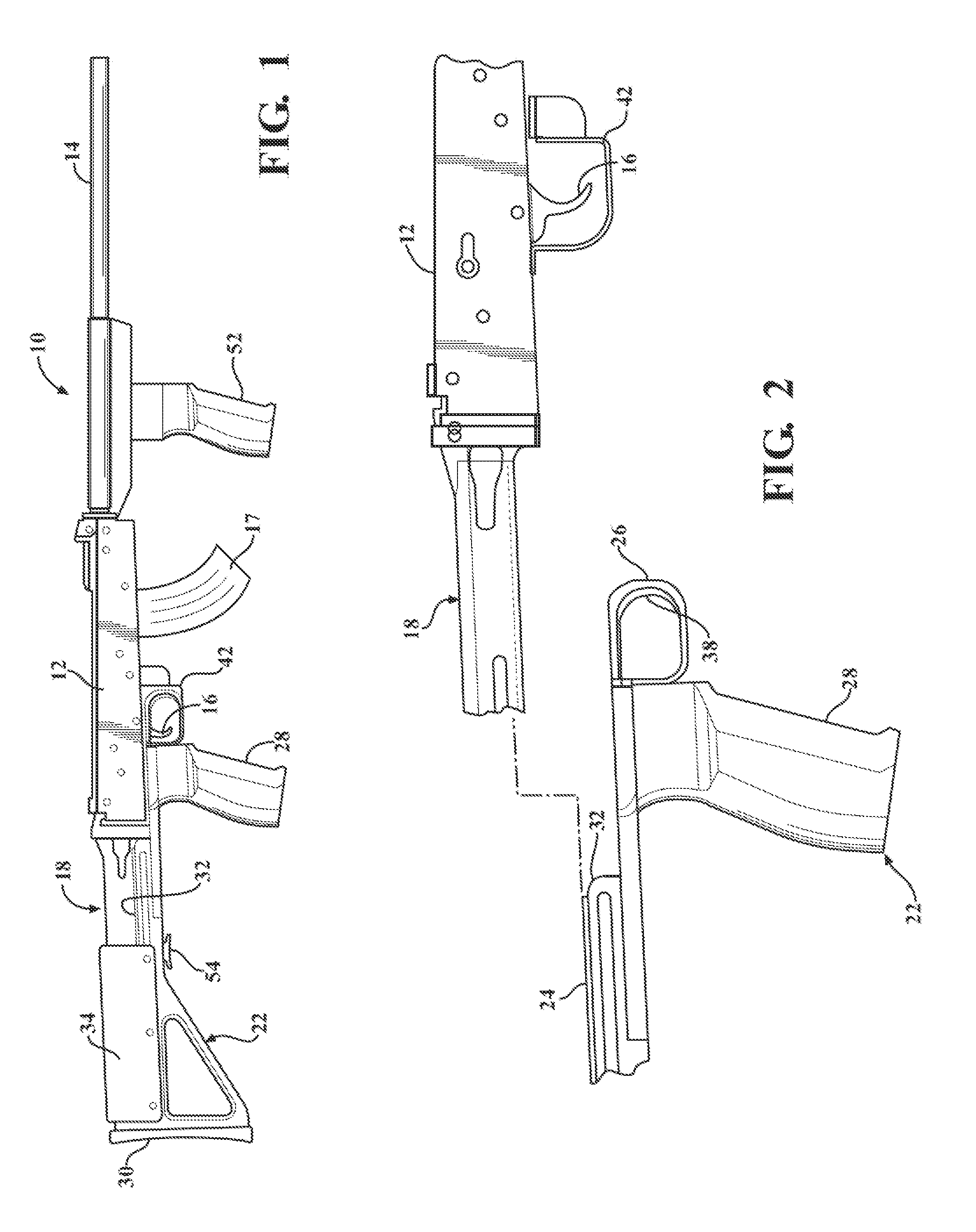
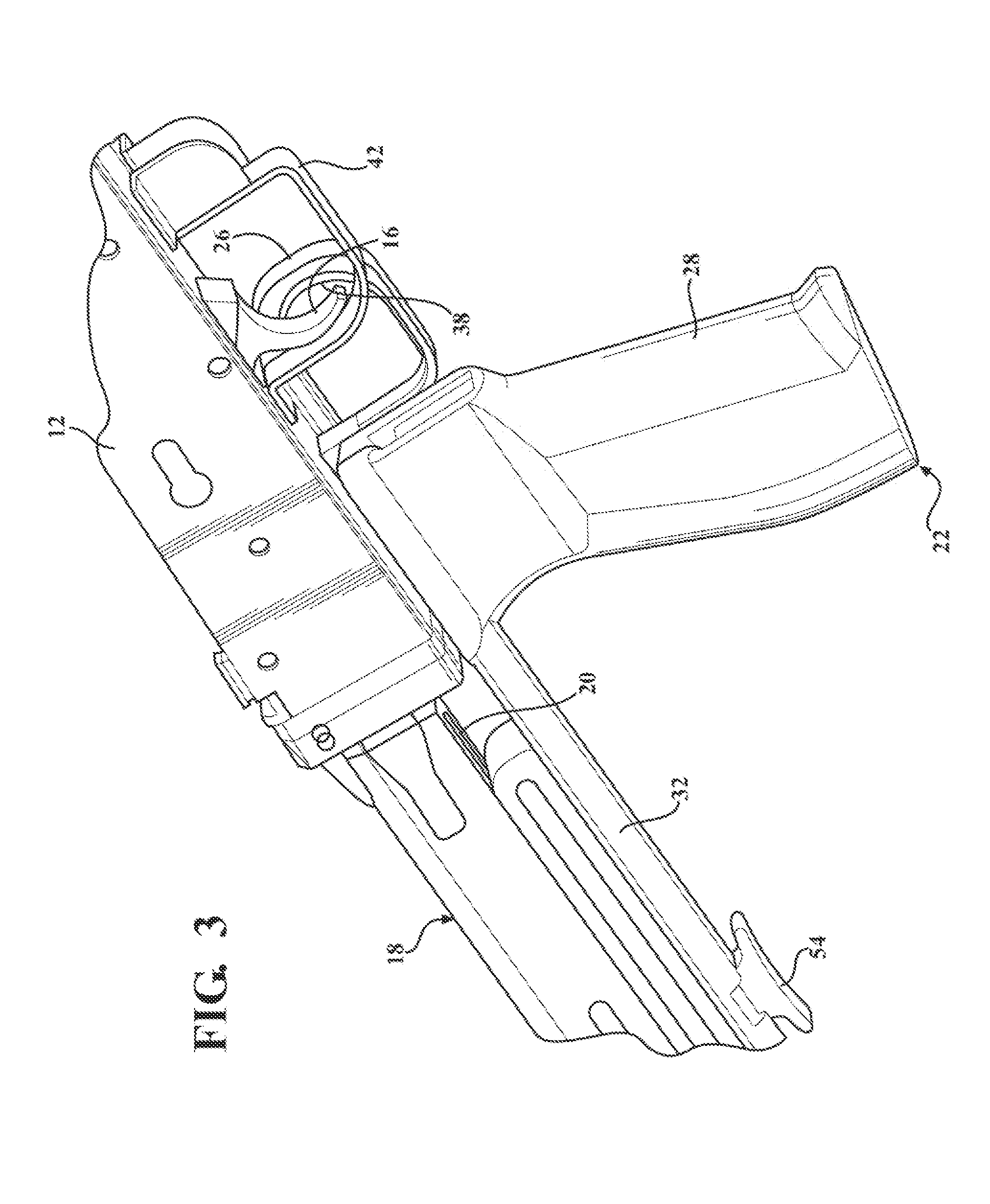
[0023]Referring to the figures wherein like numerals indicate like or corresponding parts throughout the several views, a semi-automatic firearm according to one exemplary embodiment of this invention is generally shown at 10 in FIG. 1. In the illustrated examples, the firearm 10 is depicted as a rifle or long gun; however the principles of this invention may be applied with success to hand guns and pistols. Therefore, those of skill in the art should appreciate that the term firearm as used throughout this patent application is applicable to all forms of semi-automatic projectile-firing devices.

[0024]The firearm 10 includes a receiver 12 and a barrel 14 and a trigger 16 operatively connected together as a firing unit. Ammunition (not shown) fed into the receiver 12 (such as through a magazine 17 or a belt system) is presented into a firing chamber (not shown) at the base of the barrel 14. A firing pin struck by a hammer (neither of which are shown) ignites a round of ammunition in ...


PUM


Abstract

A slide-action stock for a semi-automatic firearm. The side-action stock includes a handle provided with an integral finger rest. The finger rest forms a cradle for the user's trigger finger. In use, the user grasps the handle with one hand while pressing the dorsal side of their index finger firmly against the cradle. When intending to fire a round of ammunition, the user pushes the receiver forward with their other hand so that the trigger collides with the stabilized index finger. Recoil force quickly separates the trigger from the user's finger against the cradle. The user pushes the receiver forward to repeat the firing cycle. A firing mode selector can be selectively engaged to restrict longitudinal movement of the trigger relative to the handle, thereby returning the firearm to normal semi-automatic functionality.

Description

CROSS REFERENCE TO RELATED APPLICATIONS[0001]This application claims priority to Provisional Patent Application No. 61 / 667,777 filed Jul. 3, 2012, the entire disclosure of which is hereby incorporated by reference and relied upon.BACKGROUND OF THE INVENTION[0002]1. Field of the Invention[0003]The present invention relates generally to firearms, and more particularly toward a manually reciprocated slide-action stock for semi-automatic firearms.[0004]2. Related Art[0005]Various techniques and devices have been developed to increase the firing rate of semi-automatic firearms. Many of these techniques and devices make use of the concept known as rapid-action or “bump firing”, which is the manipulation of the recoil of the firearm to rapidly activate the trigger. One such rapid-action firing technique is known as the “belt loop” method. To execute the belt loop method, the shooter first places the firearm next to his or her hip and hooks one finger through both the trigger guard (in fron...

Claims


Application Information

Patent Timeline
Patent Type & Authority Applications(United States)
IPC IPC(8): F41A19/03F41C23/06
CPCF41A19/03F41C23/06F41A19/00
Inventor FOSTER, DAVID
Owner SLIDE FIRE SOLUTIONS
Why Eureka
Try Eureka