Using handheld device to control flying object

a handheld device and flying object technology, applied in the field of rc toys, can solve the problems of not being able to reproduce the same roll action control motion through the same type, and the ar.drone and the rc plane cannot reproduce the same type of yaw action, so as to make it much more difficult for users to learn how to properly use the remote control radio

Inactive Publication Date: 2014-01-09
CYWEE GROUP
View PDF21 Cites 261 Cited by
  • Summary
  • Abstract
  • Description
  • Claims
  • Application Information

AI Technical Summary

Benefits of technology

[0029]The present invention further provides a method to execute a power saving action that is performed by detecting a value of the flying object's height measured from the ground via one or more readings obtained from an altimeter or a pressure sensor disposed on the flying object to automatically adjust the amount of power consumption for the purpose of both maintaining the flying object at a specified height from the ground in a power saving way, and / or controlling the rotating speed of the one or more propellers or jets to prevent the flying object from crash.

Problems solved by technology

One drawback of the conventional method for remote control of a flying object is that the user must sometimes stop looking at the drone, during periods when the drone is flying under the controlled mode, to instead look at the handheld device for performing some other remote control functions (which is awkward for the user since the drone is piloted at sight) as well as having to make various fingers gestures on the touch screen of the handheld device for making additional piloting maneuvers.
Another drawback of the conventional remote-controlled plane is that for turning left or right of the RC plane, the RC plane typically relies on the making of a roll to the right or left, or banking left or right, to make such turns, rather than using a rudder to make yaw rotations.
Meanwhile, another drawback of the conventional remote control helicopter drone is that it cannot produce roll actions through the same roll action control motions as made on the handheld device acting as remote control device.
Furthermore, the AR.Drone and the RC plane both cannot reproduce yaw actions through the same type of yaw action control motions made on the handheld device itself.
Another drawback of conventional remote-control radios for controlling the piloting actions of the RC plane is that typically it is much more difficult for the user to learn how to properly use the remote control radio because it has too many adjustment items, such as including, at least two control sticks, trims; and, if the radio / transmitter set has 5 or more channels, it also has switches and rotating dials.
Meanwhile, another drawback of conventional drone quadricopters such as the AR.Drone is that it requires to have independent and precise control and adjustment of each of the four rotors attached to the four ends of a crossing of its body, where each pair of opposite rotors is turning the same rotational direction, so that one pair of rotors is turning clockwise and the other pair of rotors is turning counter-clockwise, in order to provide flight control in yaw, roll, and pitch of the drone.
Another drawback of conventional drone quadricopters is that piloting control maneuvers made by tilting or rotating the handheld device for pitch, roll and yaw angular changes or adjustments on the handheld device itself do not directly translate to actual corresponding flying object orientation changes with regards to pitch, roll, and yaw.
Another drawback of conventional drones is that it is typically not equipped with any nine-axis motion sensor having a magnetic sensor for producing output parameters such as magnetic flux, and flying object orientation value in an absolute terrestrial coordinate.
Another drawback of conventional remote control planes and helicopter type flying objects is that upon situations in which the flying object experiences any flight emergency, thereby causing the flying object to free fall from high altitude into the ground, the user through the remote control radio or the handheld device acting as remote control cannot properly save the flying object in time.
Another drawback of conventional remote control helicopter drones is that there is no automatic power saving capability, so that the drone cannot reduce or adjust the amount of power consumption and throttle when controlling the rotation speed of its propellers to maintain a particular flying height.

Method used


Image

  • Using handheld device to control flying object
  • Using handheld device to control flying object
  • Using handheld device to control flying object

Examples


second embodiment

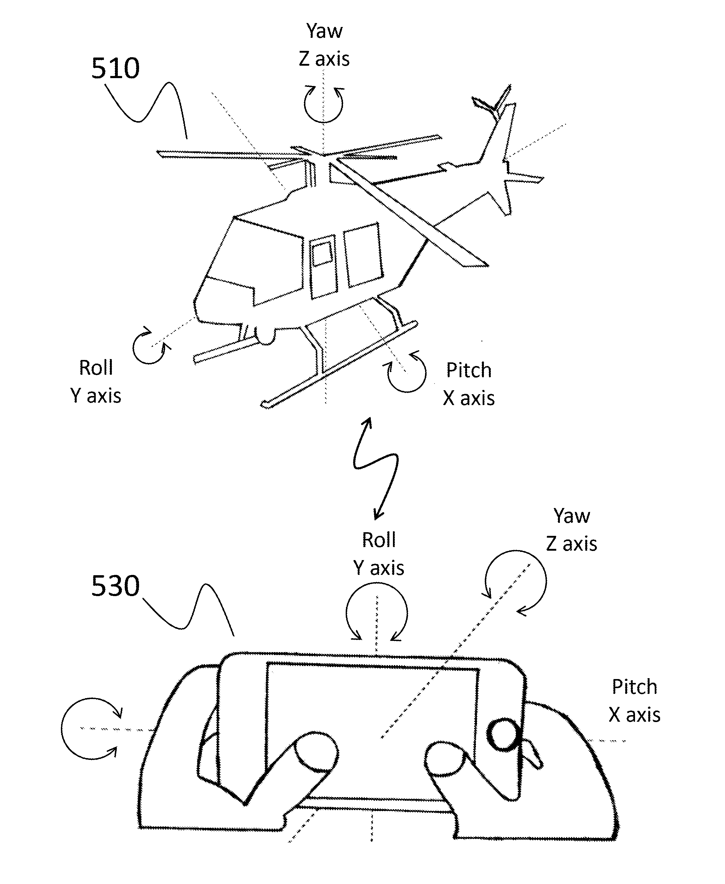
[0044]Referring to FIG. 3A, it is a block diagram of a remote-controlled flying object system 500 with a motion sensor module 540 that includes a gyro-sensor 600 and a g-sensor 605. The gyro-sensor 600 of the motion sensor module 540 comprises at least one axis (shown in FIG. 4), and the g-sensor 605 of the motion sensor module 540 comprises at least two axes. The motion sensor module 540 is provided to measure motion signals when the handheld device is operated at three-dimensional movements. The motion signals can be output parameters representative of one or more motion data in acceleration and angular speed, so as to calculate orientation values, gravity changes and linear accelerations of the flying object.

third embodiment

[0045]Referring to FIG. 3B, it is a block diagram of a remote-controlled flying object system 500 with a motion sensor module 540 that includes a gyro-sensor 600, a g-sensor 605 and a magnetic sensor 720. The gyro-sensor 600 of the motion sensor module 540 comprises at least one axis (shown in FIG. 4), the g-sensor 605 of the motion sensor module 540 comprises at least two axes, and the magnetic sensor 720 comprises three axes. The motion sensor module 540 is provided to measure motion signals when the handheld device in the form of a smartphone 530 is operated at three-dimensional movements. The motion signals can be output parameters representative of one or more motion data in acceleration, angular speed and magnetic flux, so as to calculate orientation values, gravity changes and linear accelerations of the flying object.

[0046]In the second and third embodiments, the flying object 510 is a remote control helicopter aircraft or jet aircraft. The flying object 510 is flown to a de...

fourth embodiment

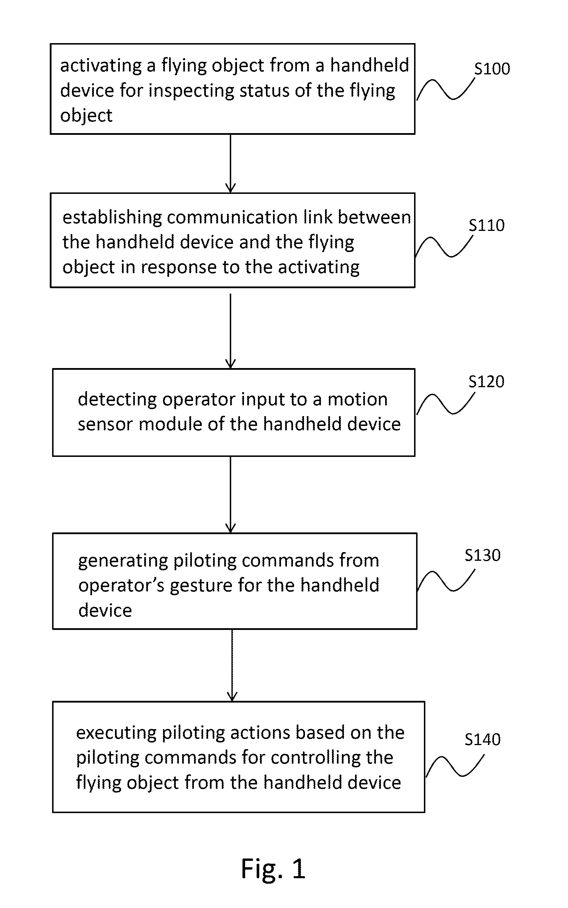
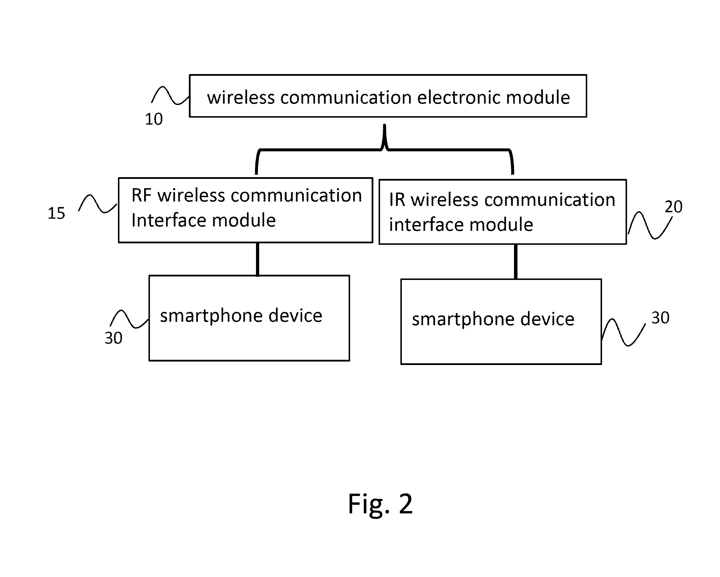
[0060]A remote-controlled flying object system for using a handheld device is disclosed herein (not shown) according to the present invention. The remote-controlled flying object system comprises a flying object, and a wireless communication unit. The flying object is attached with a g-sensor for detecting an acceleration of a gravity direction of the flying object based on one or more measurements of the acceleration so as to prevent flying crash. The wireless communication unit establishes a wireless communication link between the handheld device and the flying object via a plurality of infrared or radio-frequency signals. The handheld device further comprises a touch screen, a motion sensor module, a flight control and piloting interface and a flight control software program. The motion sensor module has a gyro-sensor and a g-sensor for measuring roll, yaw and pitch angles, and translation of the handheld device. The flight control and piloting interface is provided to display on...


PUM


Abstract

Method and system for remote control of a drone helicopter and RC plane using a handheld device is disclosed. Piloting commands and actions are performed using the handheld device, which includes a motion sensor module, with gyro-sensor and g-sensor for controlling roll, yaw and pitch of flying object under relative or absolute coordinate system. The gyro-sensor controls both heading and rotation of flying object in place around its yaw by rotating handheld device around its yaw axis; g-sensor controls pitch and roll by rotating handheld device around its pitch axis and roll axes. Upon determining free falling of flying object, throttle is thereby adjusted so as to land it safely. Flying object further has a camera, and video images are transferred wireless to be displayed on touch screen, and image zoom-in and zoom-out are provided via multi-touch of touch screen. RF and IR capability is included for wireless communication.

Description

[0001]The present invention relates to remotely controlling of a flying object, and in particular, to a method and system for remote controlling a drone, such as helicopters and the like, and an RC plane using a handheld device.BACKGROUND OF THE INVENTION[0002]Some of the most popular RC toys seen today are flying objects such as RC helicopters and airplanes. In recent years, a toy quadricopter was seen in the market. This conventional remote control drone is, for example, the AR.Drone offered by Parrot S A; it is a toy quadricopter equipped with three-axis accelerometers and gyros, an altimeter, a vertically-directed camera and an automatic stabilization system for stabilizing the drone during hovering. The AR.Drone can be remote-controlled using an iPhone®, iPod touch® or iPad™. It is also provided with a front camera for capturing real-time video images as viewed at the front of the AR.Drone itself. For the AR.drone. inertial measurements are used for automatic pitch, roll and ya...

Claims


Application Information

Patent Timeline
Patent Type & Authority Applications(United States)
IPC IPC(8): B64C13/20
CPCB64C13/20B64C2203/00B64C39/024A63H30/04A63H27/02G05D1/0016G05D1/0038B64U2201/20
Inventor YE, ZHOULU, YING-KO
Owner CYWEE GROUP
Why Eureka
Try Eureka