Vehicular power transmission device

a transmission device and transmission device technology, applied in the direction of electric devices, charging stations, transportation and packaging, etc., can solve the problems of lowering the reception power of the reception side (power reception mechanism), and achieve the effect of preventing the lowering of the reception power, reducing the reception power, and eliminating noise mixing

Active Publication Date: 2014-01-09
HONDA MOTOR CO LTD
View PDF6 Cites 4 Cited by
  • Summary
  • Abstract
  • Description
  • Claims
  • Application Information

AI Technical Summary

Benefits of technology

[0008]The aspect of the invention has been accomplished in consideration of the above-described situation, and an object of the aspect of the invention is to provide a vehicular power transmission device which is capable of preventing lowering of transmission power while eliminating noise mixing in a radio receiver when transmitting power in a noncontact manner through transmission of electromagnetic waves.
[0017]According to the aspect of (4), the transmission power is changed based on the reception power acquired by the acquisition unit. For this reason, it is possible to appropriately prevent lowering of the reception power received by the power reception unit due to change in the transmission frequency.

Problems solved by technology

However, only when the transmission frequency of electromagnetic waves on a power transmission side (power transmission mechanism) is changed, reception power on a reception side (power reception mechanism) may be lowered due to mismatching (that is, deviation between resonance points) between the transmission frequency and the reception frequency on the reception side (power reception mechanism).

Method used


Image

  • Vehicular power transmission device
  • Vehicular power transmission device
  • Vehicular power transmission device

Examples


Embodiment Construction

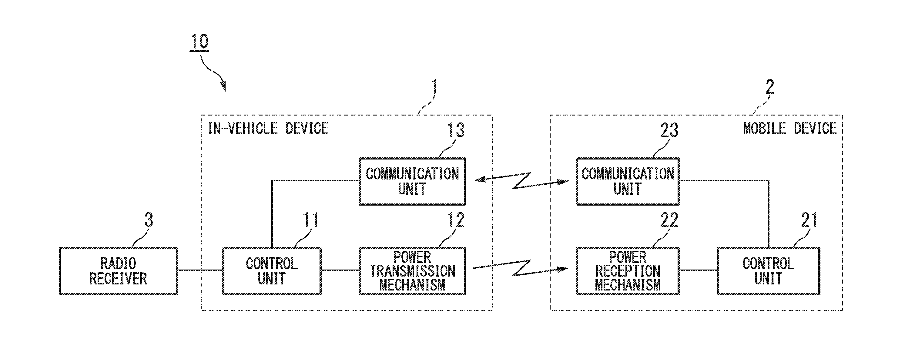
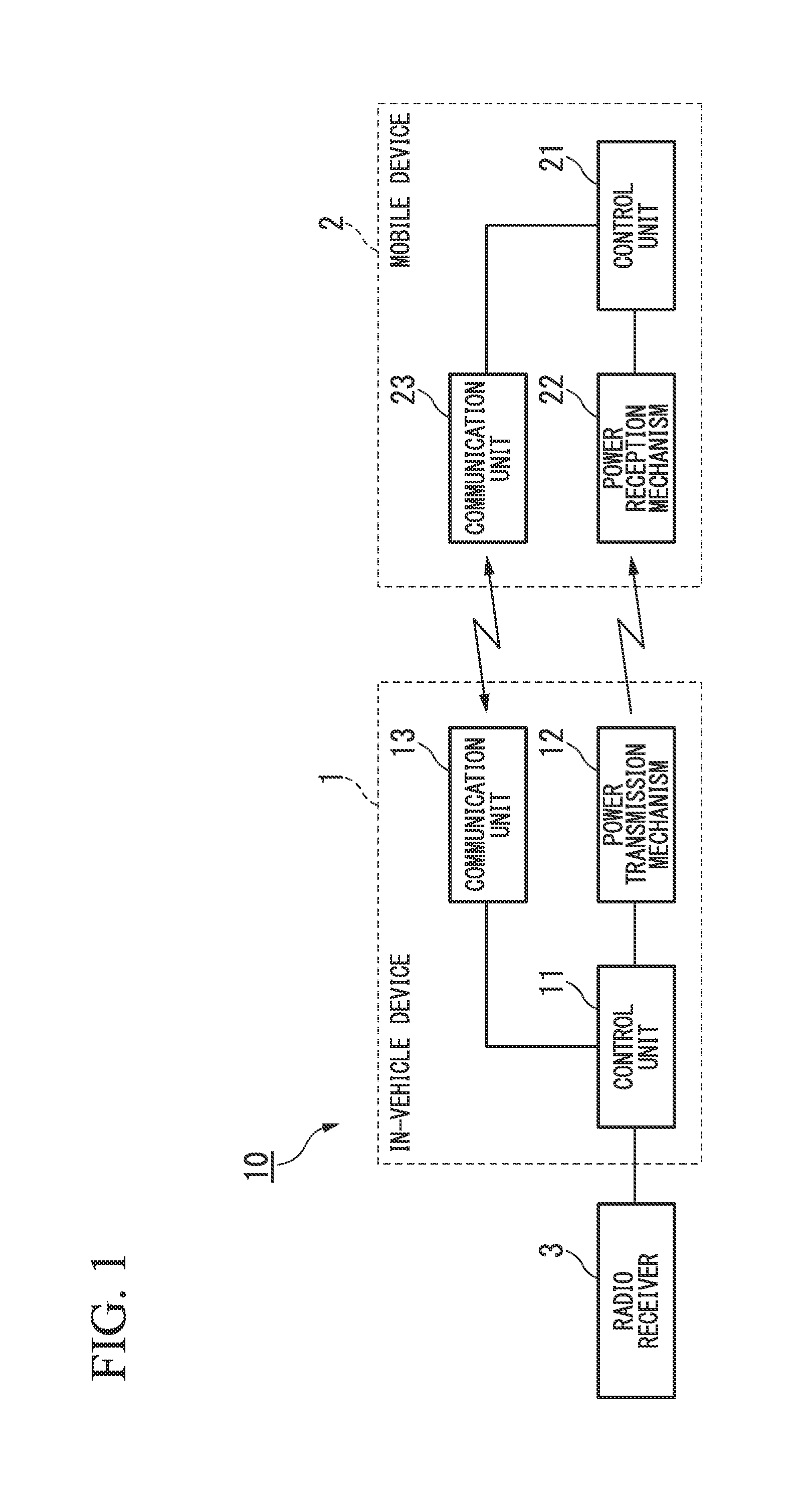
[0021]Hereinafter, a vehicular power transmission device according to an embodiment of the invention will be described with reference to the accompanying drawings. The vehicular power transmission device 10 of this embodiment is provided in an in-vehicle device 1 which is mounted in a vehicle, and eliminates noise mixing in a radio receiver 3 when transmitting power to a mobile device 2 which is carried with a passenger of the vehicle.

[0022]For example, as shown in FIG. 1, a vehicular power transmission device 10 includes a control unit 11 (frequency changing unit), a power transmission mechanism 12 (power transmission unit), and a communication unit 13.

[0023]For example, the vehicular power transmission device 10 can perform wireless communication with the mobile device 2 and is communicably connected to the radio receiver 3 in a wired manner.

[0024]For example, the control unit 11 can acquire the reception frequency (radio frequency) of the radio receiver 3 through communication wi...


PUM


Abstract

A vehicular power transmission device includes a power transmission unit which transmits electromagnetic waves to a mobile device to transmit power to a power reception unit of the mobile device, and a frequency changing unit which, when it is determined based on the transmission frequency of the electromagnetic waves to be transmitted from the power transmission unit to the mobile device and a reception frequency of a radio receiver that radio noise is generated by the power transmission unit, changes the transmission frequency of the electromagnetic waves of the power transmission unit, wherein the power transmission unit changes a transmission power of the electromagnetic waves based on an amount of change in the transmission frequency of the electromagnetic waves changed by the frequency changing unit.

Description

CROSS-REFERENCE TO RELATED APPLICATION[0001]Priority is claimed on Japanese Patent Application No. 2012-150535, filed on Jul. 4, 2012, the content of which is incorporated herein by reference.BACKGROUND OF THE INVENTION[0002]1. Field of the Invention[0003]The present invention relates to a vehicular power transmission device.[0004]2. Description of Related Art[0005]In the related art, a control device in which, when driving and controlling an electric motor of an electrically driven power steering device of a vehicle by a pulse width modulation (PWM) control signal, the driving frequency of the electric motor is changed based on a signal output from a radio receiver is known (for example, see Japanese Patent No. 3688437).SUMMARY OF THE INVENTION[0006]On the other hand, for example, when a control operation by the control device of the related art is applied to a wireless power transmission technique which transmits power in a noncontact manner by transmission of electromagnetic wave...

Claims


Application Information

Patent Timeline
Patent Type & Authority Applications(United States)
IPC IPC(8): H02J17/00
CPCH02J17/00Y02T90/14H04B15/04Y02T10/7072B60L53/12H02J50/80H02J7/00034Y02T90/16Y02T10/70H02J50/20Y02T90/12
Inventor KANAHARA, HIROKAZUARIE, SHINICHIMISHIO, YOSHIHIROKANASUGI, KATSUMI
Owner HONDA MOTOR CO LTD
Why Eureka
Try Eureka