Jig for split cage and method of assembling rolling bearing

Inactive Publication Date: 2014-01-16
JTEKT CORP
View PDF3 Cites 20 Cited by
  • Summary
  • Abstract
  • Description
  • Claims
  • Application Information

AI Technical Summary

Benefits of technology

[0010]An object of the present invention is to provide a jig for a split cage, which facilitates the assembly of a rolling bearing including a split cage configu

Problems solved by technology

However, it is difficult to integrally form a synthetic resin cage having a large diameter by injection molding.
Thus, it is diffi

Method used


Image

  • Jig for split cage and method of assembling rolling bearing
  • Jig for split cage and method of assembling rolling bearing
  • Jig for split cage and method of assembling rolling bearing

Examples


Embodiment Construction

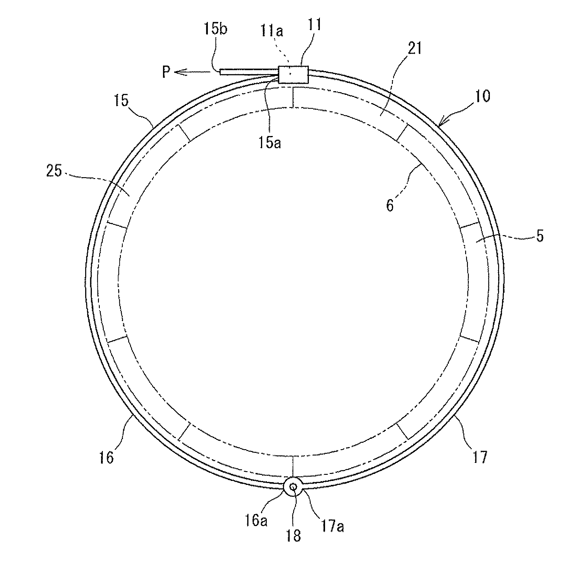
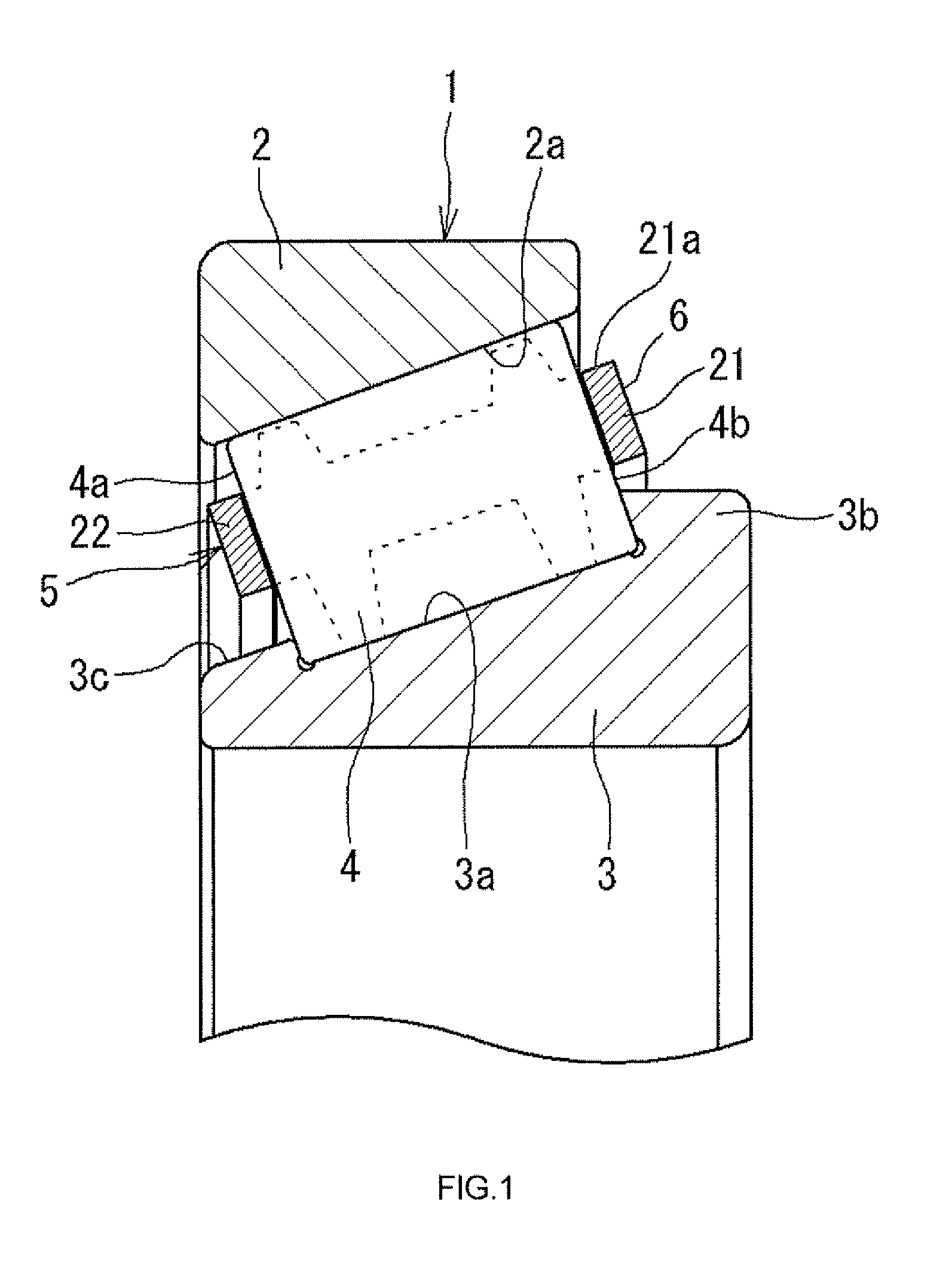
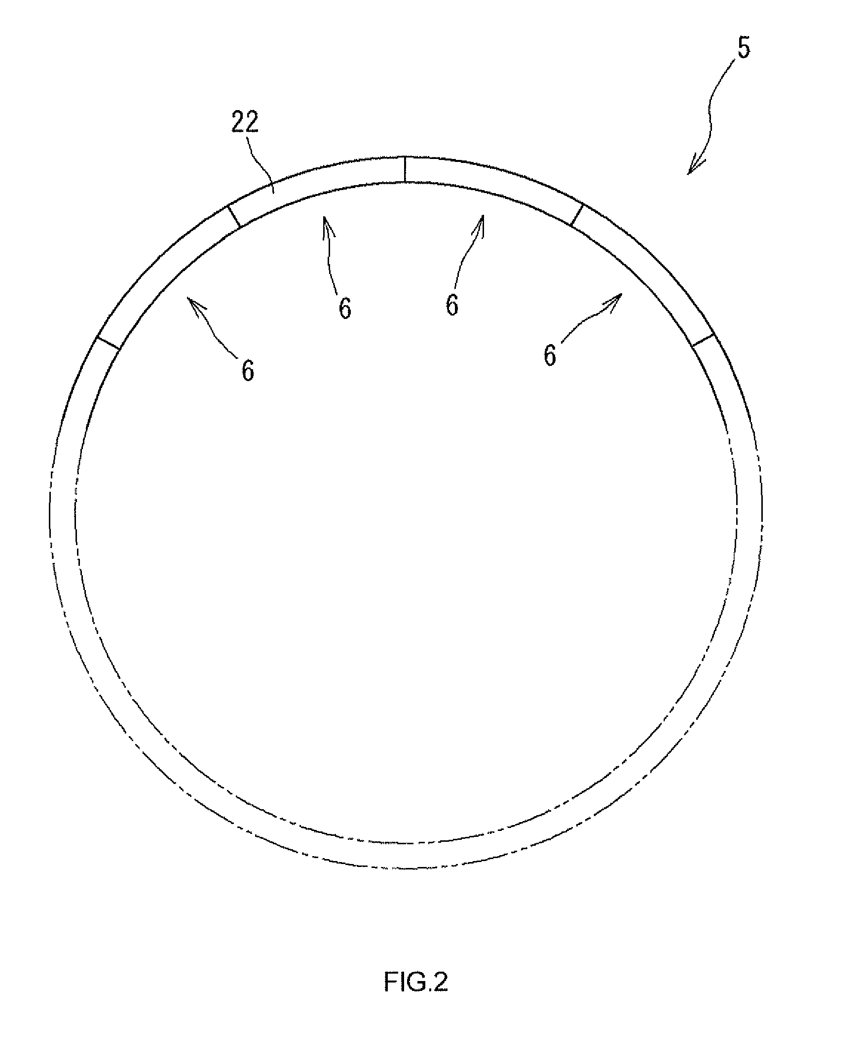
[0021]Hereinafter, embodiments of the present invention will be described. FIG. 1 is a sectional view illustrating a rolling bearing. FIG. 2 is a schematic view illustrating a cage for the rolling bearing as seen in an axial direction. The rolling bearing shown in FIG. 1 is a tapered roller bearing 1 including a plurality of tapered rollers 4 as rolling elements. The tapered roller bearing 1 is a large-sized tapered roller bearing used to support a main shaft of a wind power generation apparatus. The tapered roller bearing 1 includes an outer ring 2, an inner ring 3, the tapered rollers 4 and the cage. The tapered rollers 4 are interposed between the outer ring 2 and the inner ring 3. The cage holds the tapered rollers 4 at circumferentially equal intervals. As shown in FIG. 2, the cage is a split cage 5 that is circumferentially split into a plurality of segments. Namely, the split cage 5 is formed of a plurality of cage segments 6.

[0022]Referring to FIG I, an outer raceway surface...


PUM

PropertyMeasurementUnit
Lengthaaaaaaaaaa
Diameteraaaaaaaaaa

Abstract

A split cage is configured by annularly arranging cage segments in a circumferential direction. Each cage segment includes a pair of first and second rim portions spaced from each other by a predetermined interval and facing each other, and bar portions extending from the first rim portion to the second rim portion. Spaces, each of which is surrounded by the adjacent bar portions and the first and second rim portions, are formed as pockets that house rolling elements. A jig for the split cage includes a looped band wound on an outer peripheral side of the first or second rim portions of the cage segments annularly arranged. The band includes a lock portion that is able to adjust a loop length of the band with respect to an outer peripheral length of the first or second rim portions, and that is able to fix the adjusted loop length.

Description

INCORPORATION BY REFERENCE[0001]The disclosure of Japanese Patent Application No. 2012-156637 filed on Jul. 12, 2012 including the specification, drawings and abstract is incorporated herein by reference in its entirety.BACKGROUND OF THE INVENTION[0002]1. Field of the Invention[0003]The present invention relates to a jig for a split cage configured by annularly arranging a plurality of cage segments, and relates to a method of assembling a rolling bearing.[0004]2. Description of Related Art[0005]In conventional horizontal axis propeller type wind power generation apparatuses, rolling bearings are used to rotatably support a main shaft to which blades are attached. In recent years, since the sizes of the wind power generation apparatuses are increased, the diameter of the main shaft may exceed several meters. In order to support such a large-sized main shaft, the size of the rolling bearing is also increased. A cage formed of synthetic resin may be used for such a large-sized rolling...

Claims


Application Information

Patent Timeline
IPC IPC(8): F16C33/46B25B27/14
CPCF16C33/46B25B27/14F16C41/04F16C43/04F16C19/364F16C33/513F16C2300/14F16C2360/31F16C33/4635Y10T29/53104Y10T29/49686F16C33/502
Inventor MIYACHI, TAKESHI
Owner JTEKT CORP
Why Eureka
Try Eureka