
Indirect measurement of relative air humidity

a technology of relative air humidity and indirect measurement, which is applied in the direction of electrical control, instruments, machines/engines, etc., can solve the problem of relatively difficult to accurately measure relative air humidity, and achieve the effect of improving efficiency

Active Publication Date: 2014-01-16
FORD GLOBAL TECH LLC
View PDF10 Cites 16 Cited by
  • Summary
  • Abstract
  • Description
  • Claims
  • Application Information

AI Technical Summary

Benefits of technology

The present invention provides a method for accurately measuring relative air humidity without the need for a separate sensor. This method is simple and efficient.

Problems solved by technology

But here there is the problem that the relative air humidity is relatively difficult to measure accurately and with a small delay over the great range of the fluctuation of temperatures that can occur in a fresh air induction tube.

Method used


Image

  • Indirect measurement of relative air humidity
  • Indirect measurement of relative air humidity
  • Indirect measurement of relative air humidity

Examples


Embodiment Construction

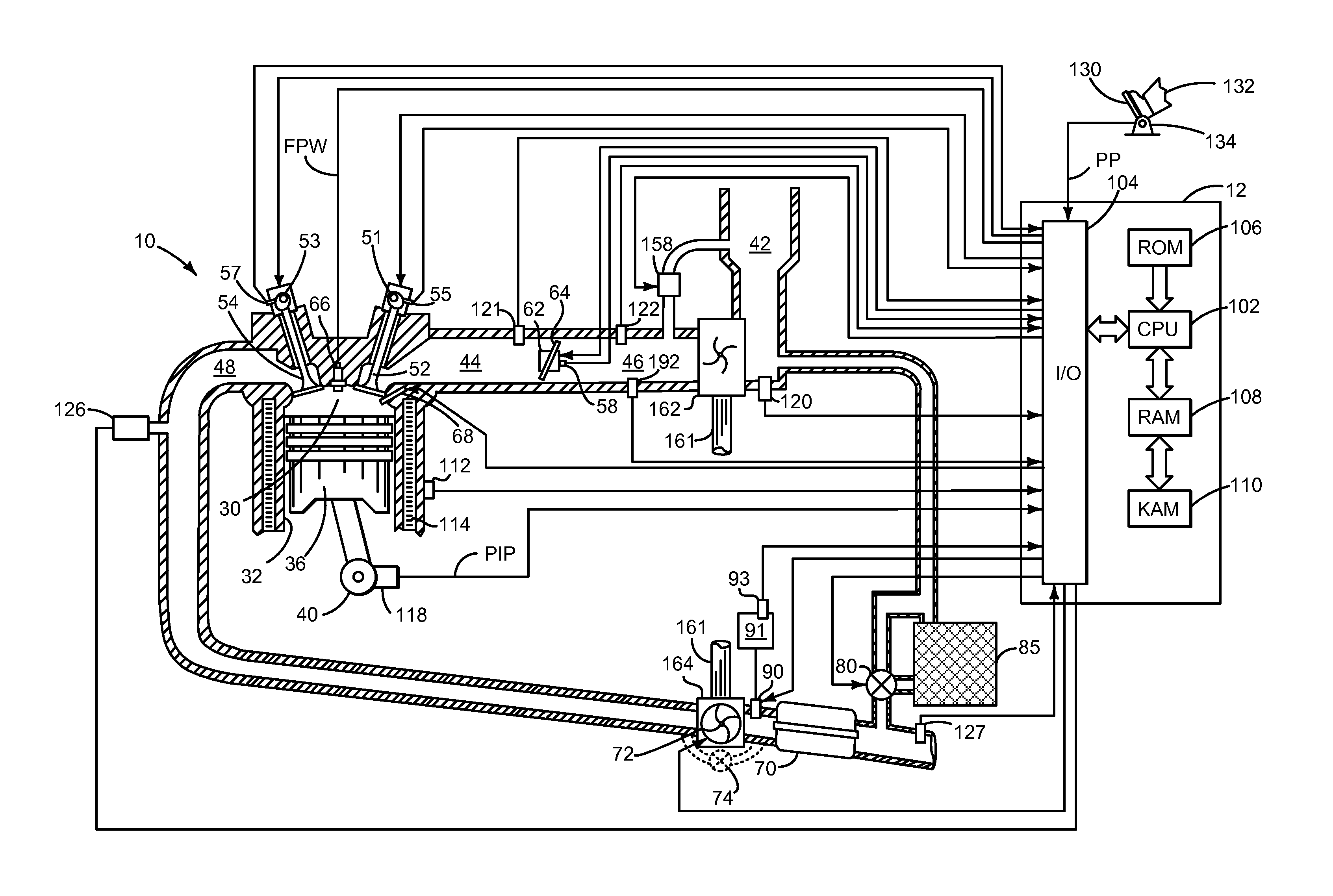
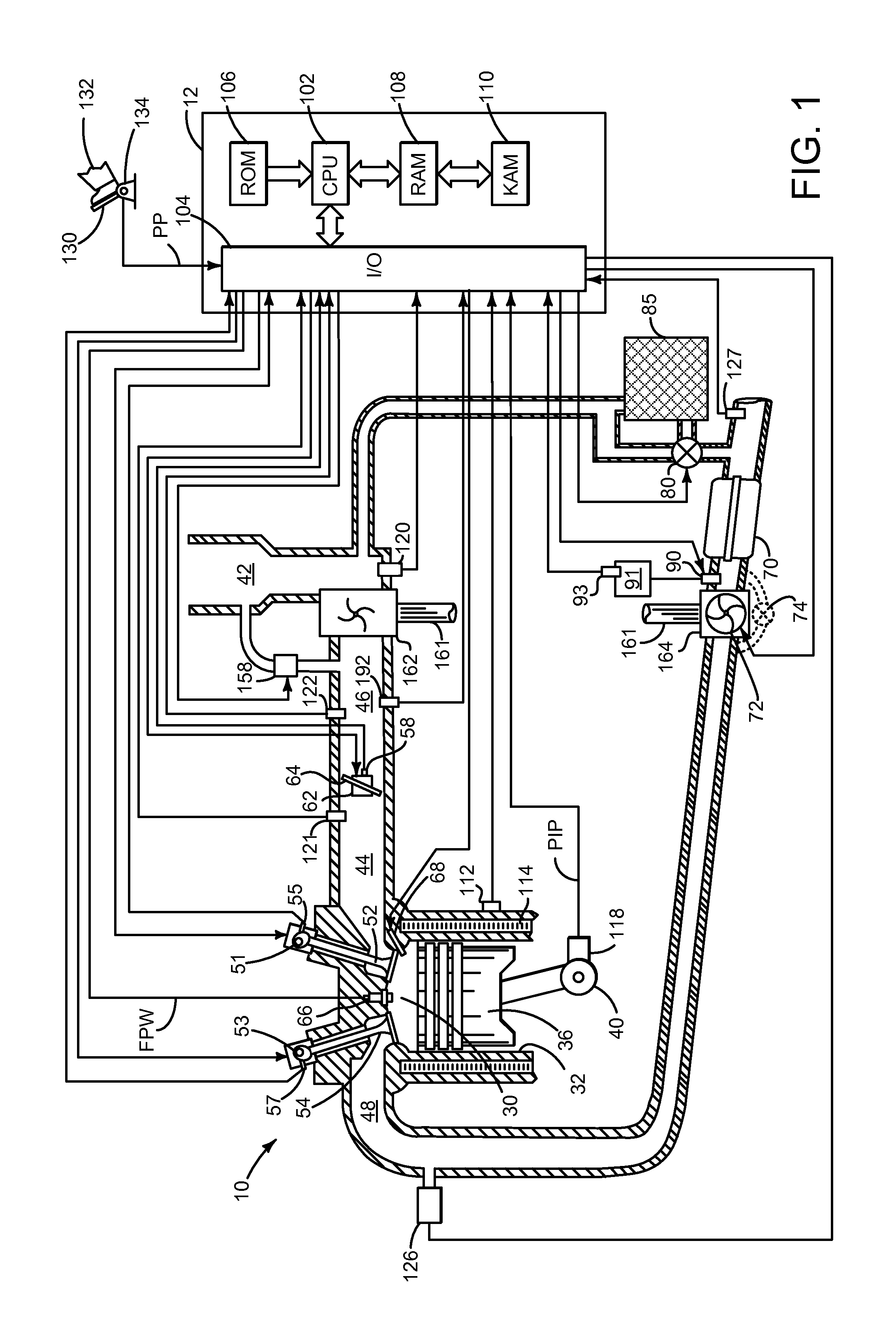
[0012]Referring to FIG. 1, internal combustion engine 10, comprising a plurality of cylinders, one cylinder of which is shown in FIG. 1, is controlled by electronic engine controller 12. Engine 10 includes combustion chamber 30 and cylinder walls 32 with piston 36 positioned therein and connected to crankshaft 40. Combustion chamber 30 is shown communicating with intake manifold 44 and exhaust manifold 48 via respective intake valve 52 and exhaust valve 54. Each intake and exhaust valve may be operated by an intake cam 51 and an exhaust cam 53. The position of intake cam 51 may be determined by intake cam sensor 55. The position of exhaust cam 53 may be determined by exhaust cam sensor 57.

[0013]Fuel injector 66 is shown positioned to inject fuel directly into combustion chamber 30, which is known to those skilled in the art as direct injection. Fuel injector 66 delivers fuel in proportion to the pulse width of signal FPW from controller 12. Fuel is delivered to fuel injector 66 by a...


PUM


Abstract

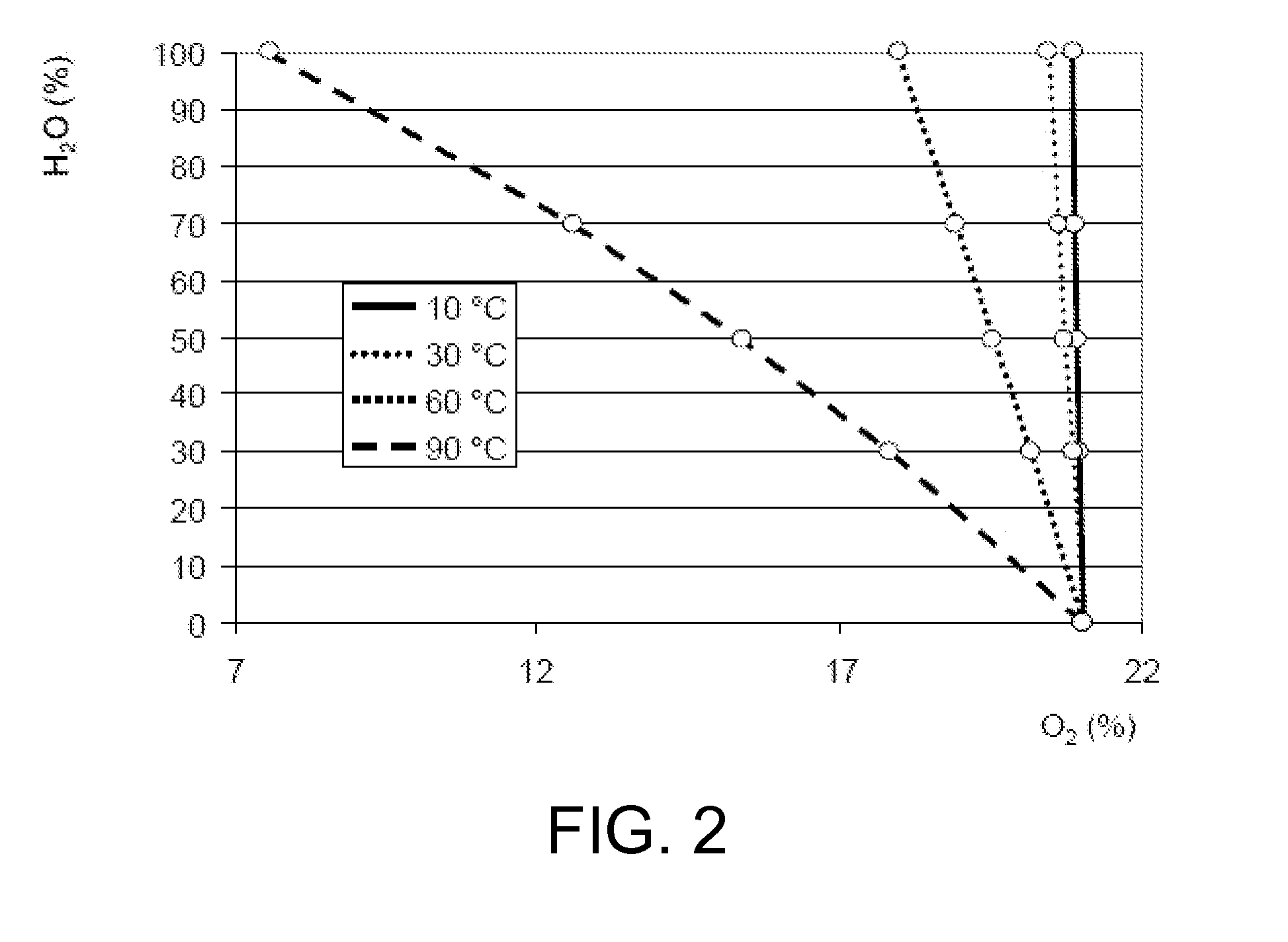
The disclosure relates to a method for the measurement of relative air humidity in a fresh air induction tube of an internal combustion engine. Here a concentration of oxygen in the fresh air induction tube is measured by an oxygen sensor and a temperature in the fresh air induction tube is determined. The relative air humidity is determined depending on the measured concentration of oxygen and the determined temperature.

Description

CROSS REFERENCE TO RELATED APPLICATIONS[0001]The present application claims priority to German Patent Application No. 102012212234.6, filed on Jul. 12, 2012, the entire contents of which are hereby incorporated by reference for all purposes.FIELD[0002]The disclosure relates to a method for the measurement of relative air humidity in a fresh air induction tube of an internal combustion engine.BACKGROUND AND SUMMARY[0003]The air humidity of the fresh air that is delivered to an internal combustion engine as part of the fuel mixture influences the combustion process. Here the water vapor admixed by means of the air humidity reduces the combustion temperature, whereby in particular fewer harmful and unwanted nitrogen oxides occur. For this reason there is a desire to measure the relative air humidity of the fresh air in order to be able to model and, if appropriate, to control the quantities of contaminants occurring during the combustion process. If the relative air humidity is known, ...

Claims


Application Information

Patent Timeline
Patent Type & Authority Applications(United States)
IPC IPC(8): F02D41/14G01M15/04
CPCF02D41/144G01M15/04F02D41/0065F02D41/005F02D2200/0414F02D2200/0418Y02T10/12Y02T10/40
Inventor YACOUB, YASSER MOHAMED SAYEDVIGILD, CHRISTIAN WINGE
Owner FORD GLOBAL TECH LLC
Learn More