
Motor and electric apparatus equipped with same

Active Publication Date: 2014-01-16
PANASONIC INTELLECTUAL PROPERTY MANAGEMENT CO LTD
View PDF7 Cites 5 Cited by
  • Summary
  • Abstract
  • Description
  • Claims
  • Application Information

AI Technical Summary

Benefits of technology

The patent text describes a motor structure that can easily change the electrostatic capacitance between the outer and inner cores, which helps to maintain the proper shaft voltage. This structure also helps to prevent electrolytic corrosion and ensures that the motor operates effectively. The technical effect of this patent is to provide a motor that is more reliable and durable, as well as an electric apparatus that includes the motor.

Problems solved by technology

The shaft voltage includes a high-frequency component attributable to switching operation, and micro electric current flows inside the bearing when the shaft voltage reaches a breakdown voltage of an oil film inside the bearing, thereby causing electrolytic corrosion in the bearing.
When the electrolytic corrosion progresses, a phenomenon of wavy wear appears on the outer ring, inner ring or balls of the bearing, thereby leading to abnormal sound noise which becomes one of the main causes of troubles of the motor.
In conventional techniques like the above example, however, there is a limitation in setting the shaft voltage appropriately though it has an effect of reducing a high frequency voltage induced in an inner ring of the bearing by making use of an electrostatic capacitance of the dielectric layer.
However, sizes of motors used in electric apparatuses are normally determined according to individual types of the electric apparatuses, and sizes of their rotors are generally standardized such that it is difficult to substantially alter the sizes, or to change the shape of dielectric layers in a flexible manner.
Although a resin material and the like need to be changed in order to change a dielectric constant of the insulation resin that forms the dielectric layer, it is not easy to make any change in the material since such a change makes it necessary to confirm other points such as the strength.
The conventional technique thus has a limitation in setting the dielectric layer in a manner to make the shaft voltage become optimum.

Method used


Image

  • Motor and electric apparatus equipped with same
  • Motor and electric apparatus equipped with same
  • Motor and electric apparatus equipped with same

Examples


first exemplary embodiments

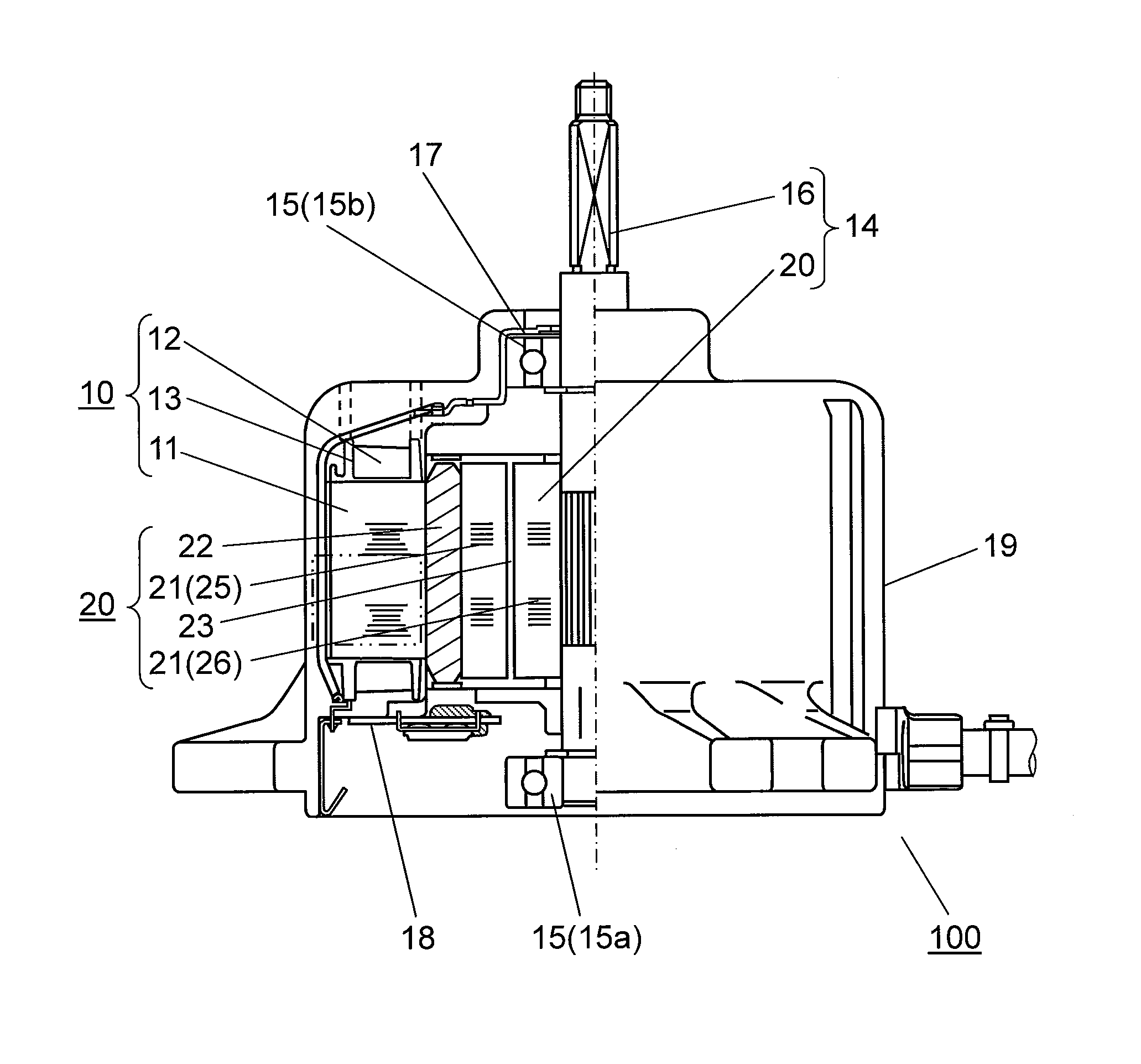
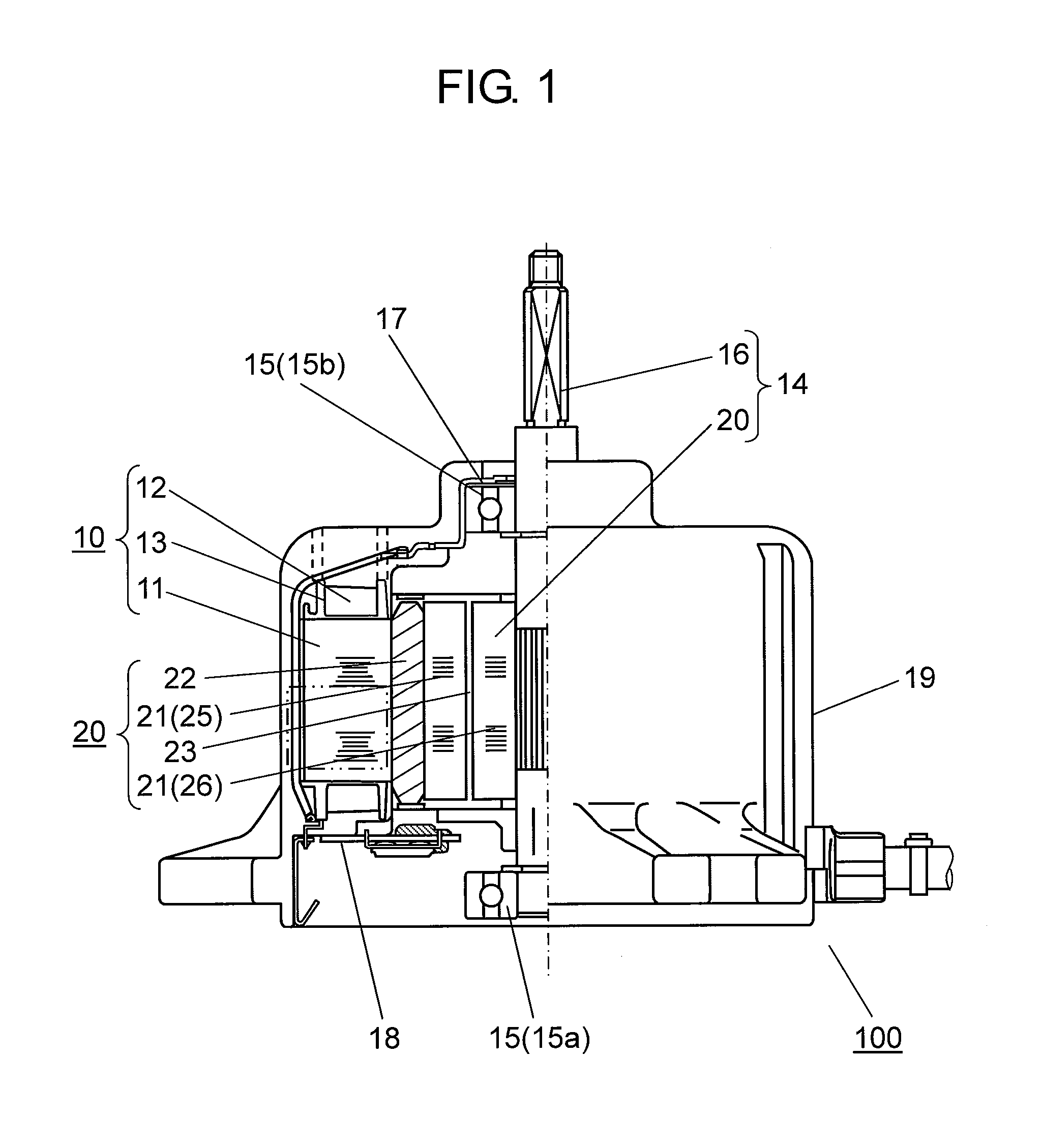
[0016]FIG. 1 is a structural drawing showing a cross section of brushless motor 100 according to the first exemplary embodiment of this invention. In this embodiment, description is given of one example of brushless motor as a representative of the motor adaptable for mounting to an electric apparatus. In addition, the example described in this embodiment is an inner-rotor type motor having a rotor disposed rotatably to the interior side of a stator.

[0017]In FIG. 1, stator winding 12 is wound on iron stator core 11 with insulation resin 13 interposed as an insulator for isolating stator core 11. Stator core 11 of this structure is fixed into motor case 19 together with other stationary members, and composes stator 10 having an outer appearance of generally a cylindrical shape. Stator 10 may have such a structure as to be molded with an insulation resin, for instance, as a molding material.

[0018]Rotor 14 is inserted inside stator 10 with an air gap between them. Rotor 14 includes rot...

second exemplary embodiment

[0037]As an example of electric apparatus according of the present invention, description is provided in detail of a structure of an indoor unit of air conditioner as the second exemplary embodiment. In FIG. 5, motor 201 is mounted inside enclosure 211 of air conditioner's indoor unit 210. Cross-flow fan 212 is attached to a rotary shaft of motor 201. Motor 201 is driven by motor driving device 213. Motor 201 rotates when energized by motor driving device 213, and cross-flow fan 212 rotates with it. Air that is conditioned by a heat exchanger (not shown) of the indoor unit is delivered into a room by the rotation of cross-flow fan 212. Here, brushless motor 100 of the first embodiment described above, for instance, is applicable as motor 201.

[0038]In the description above, although the motor mountable to an air conditioner's outdoor unit or an indoor unit is shown as an exemplary embodiment of the electric apparatus, the present invention is also applicable to other motors that are ...


PUM


Abstract

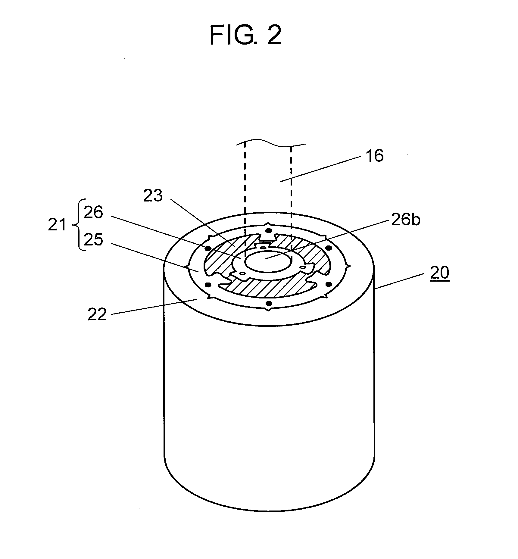
A motor of the invention has a rotary body of a rotor, and the rotary body includes an outer core constituting an outer portion of the rotary body, an inner core constituting an inner portion connected to a shaft, and a dielectric layer disposed between the outer core and the inner core. The outer core has a protruding portion that protrudes inward from an inner surface thereof, and the inner core has a protruding portion that protrudes outward from an outer surface thereof, wherein the outer core and the inner core are so disposed that an end face of the protruding portion of the outer core and an end face of the protruding portion of the inner core confront partially with respect to each other.

Description

RELATED APPLICATIONS[0001]This application claims priority under 35 U.S.C. §119 to Japanese Patent Application No. 2012-155305 filed on Jul. 11, 2012, the entire content of which is hereby incorporated by reference.TECHNICAL FIELD[0002]The present invention relates to a motor and an electric apparatus equipped with the same, and more particularly, to a motor with improvements to suppress development of electrolytic corrosion of a bearing, and an electric apparatus equipped with the same.BACKGROUND ART[0003]There is a continuous increase in number of cases in which electric motors are driven by using inverters of pulse-width modulation method (hereinafter referred to as “PWM method”). In such a case where a motor is driven with an inverter of the PWM method, a difference in electric potential occurs between an outer ring and an inner ring of a bearing (referred to as “shaft voltage”) since an electric potential at a neutral point of a winding does not stay at 0 (zero) volt. The shaft...

Claims


Application Information

Patent Timeline
IPC IPC(8): H02K5/16
CPCH02K5/16H02K1/04H02K1/30H02K5/1732H02K11/40
Inventor KOWA, TAKESHIKAWASAKI, HIROAKIWATANABE, AKIHIKOMAETANI, TATSUOISOMURA, YOSHINORI
Owner PANASONIC INTELLECTUAL PROPERTY MANAGEMENT CO LTD
Learn More