
Power conversion apparatus and controlling method thereof

a technology of power conversion apparatus and controlling method, which is applied in the direction of power conversion systems, instruments, circuit arrangements, etc., can solve the problems of increasing power factor loss, increasing passive architecture not being able to actively control and adjust power factors, etc., to achieve low power consumption of switching elements, reduce current harmonic wave of output signals, and high efficiency energy conversion

Active Publication Date: 2014-01-16
DELTA ELECTRONICS INC
View PDF4 Cites 26 Cited by
  • Summary
  • Abstract
  • Description
  • Claims
  • Application Information

AI Technical Summary

Benefits of technology

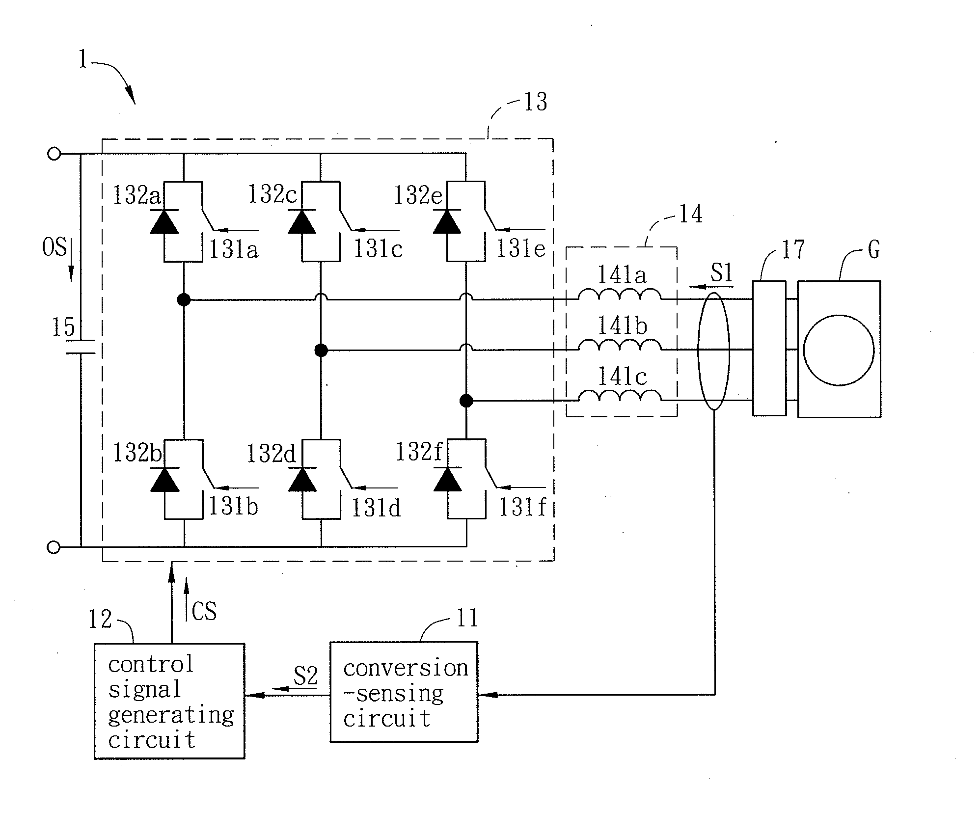
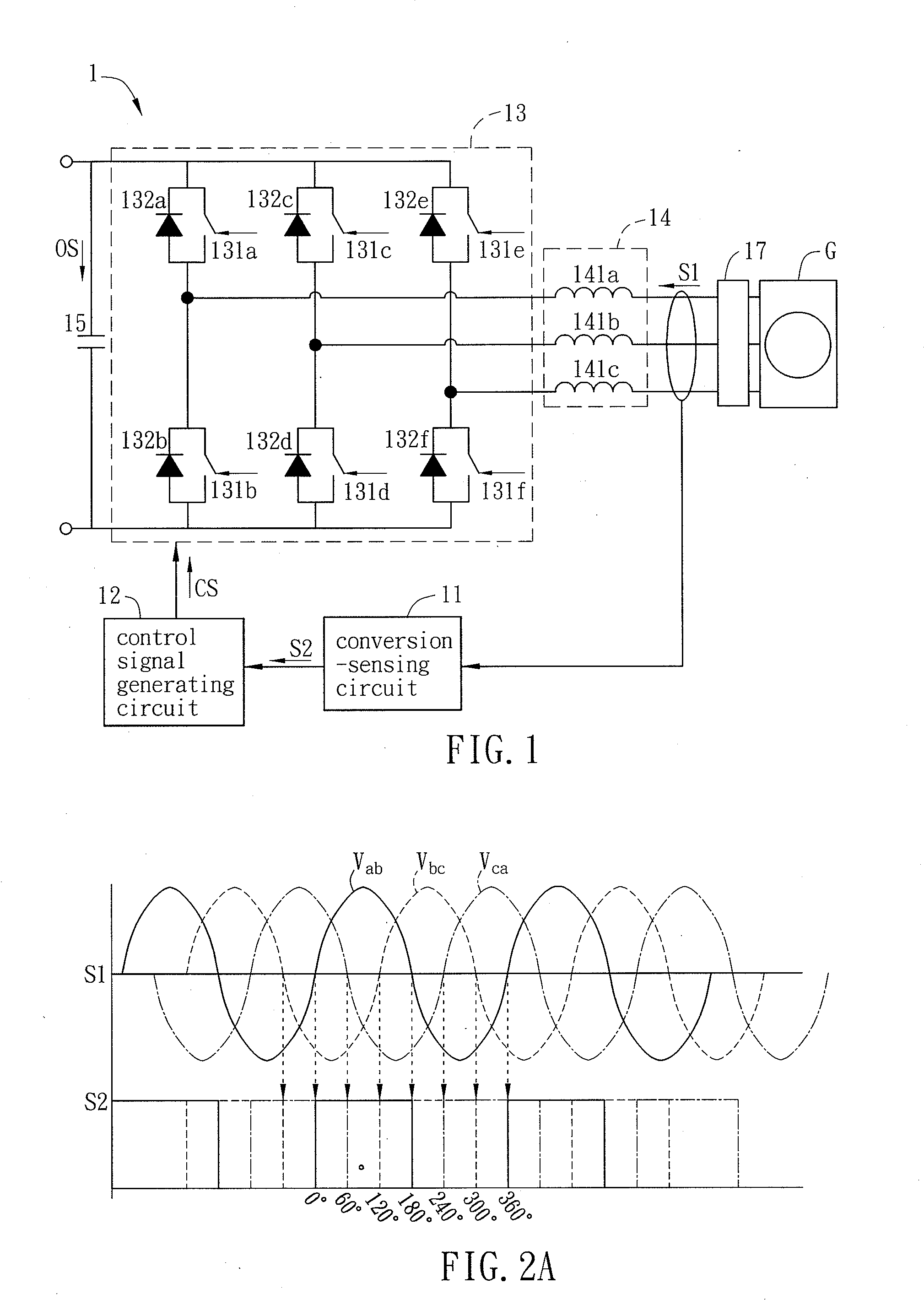
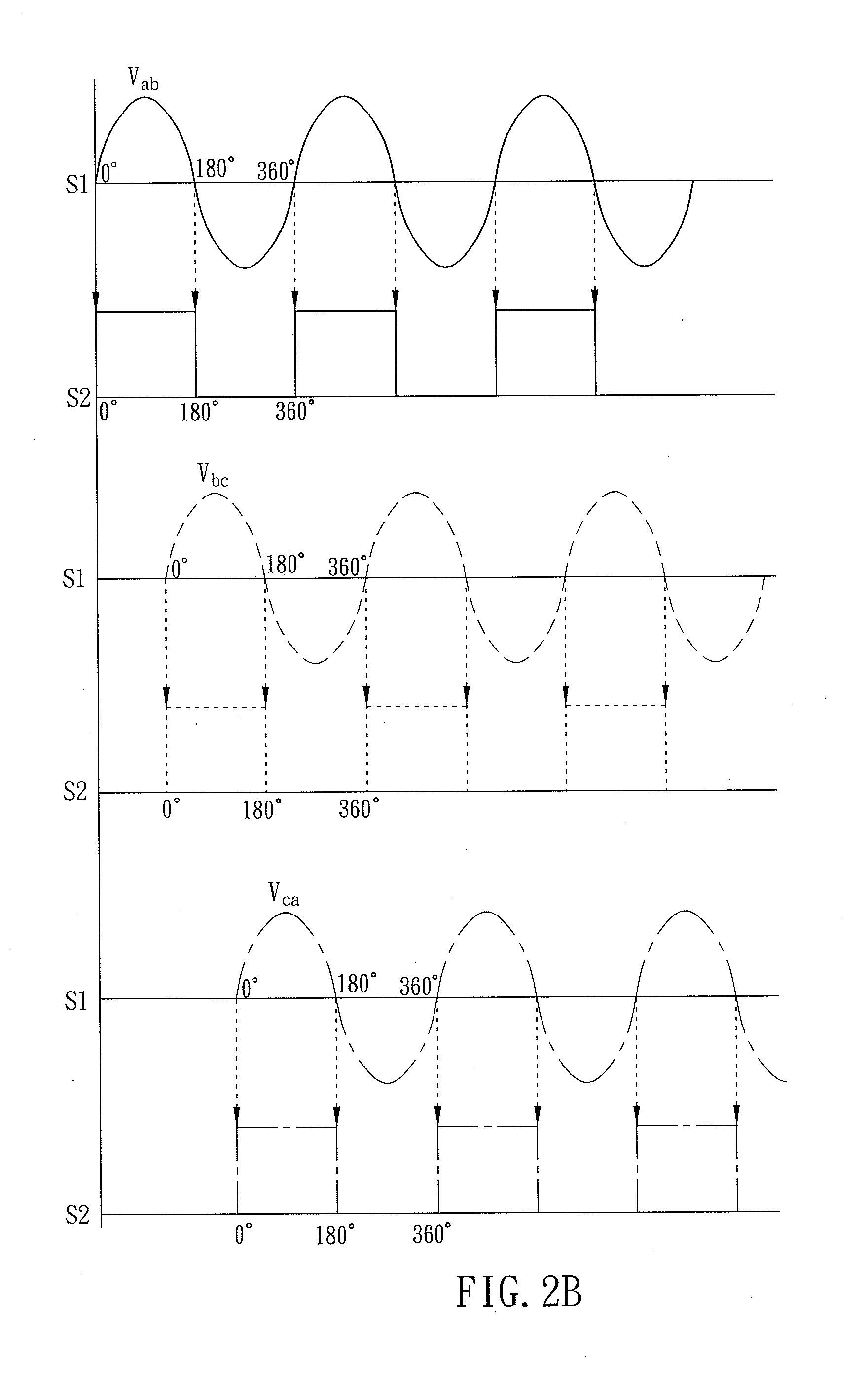
The invention provides a power conversion apparatus and method with full power and high efficiency energy conversion and lower power loss. It utilizes a conversion-sensing circuit to obtain the instantaneous rotating speed and frequency of the power generation apparatus and achieve the control of the instantaneous rotating speed, eliminating the need for a separate position detector. The control signal generating circuit outputs a control signal based on the time interval, controlling one of the switching elements of a switching circuit to turn on and off, minimizing power consumption and current harmonic wave of the output signal. Overall, the power conversion apparatus has full power and high efficiency energy conversion.

Problems solved by technology

Because the use of only a single switch can achieve the energy conversion, the energy loss of the apparatus is extremely small.
However, the passive architecture cannot actively control and adjust the power factor, and the loss thereof also proportionally rises with the increases of the power and the current.
When being applied to the middle or high wind speed or the high power wind generator, the power loss of the apparatus upon conversion is relatively high.
However, the active architecture needs to drive six active switches to operate concurrently and needs to supply the power to the position detector disposed on the generator to have the long distance line loss, so that the power loss is much larger than that of the passive system.
Thus, the active architecture is not advantageous to the wind energy conversion for the low wind speed or the low power wind generator.

Method used


Image

  • Power conversion apparatus and controlling method thereof
  • Power conversion apparatus and controlling method thereof
  • Power conversion apparatus and controlling method thereof

Examples


Embodiment Construction

[0029]The present invention will be apparent from the following detailed description, which proceeds with reference to the accompanying drawings, wherein the same references relate to the same elements.

[0030]FIG. 1 is a schematic illustration showing a power conversion apparatus 1 according to a preferred embodiment of the invention. Referring to FIG. 1, a power conversion apparatus 1 may be applied with a power generation apparatus G. The power generation apparatus G may output a first signal S1, which is a three-phases balanced sine wave voltage signal with the stable phase sequence. The power generation apparatus G may be, for example but without limitation to, a wind power generator of a wind power generation system, and may also be another power generation apparatus, such as a thermal power generation apparatus, a waterpower power generation apparatus, a solar power generation apparatus or any other power generation apparatus. In addition, the output, after the conversion of th...


PUM


Abstract

A power conversion apparatus and a controlling method thereof are disclosed. The power conversion apparatus is applied with a power generation apparatus, which outputs a first signal. The power conversion apparatus includes a conversion-sensing circuit, a control signal generating circuit and a switching circuit. The conversion-sensing circuit converts the first signal into a second signal, and senses at least a voltage waveform change of the second signal to generate a time interval. The control signal generating circuit is electrically connected with the conversion-sensing circuit and outputs a control signal according to the time interval. The switching circuit is electrically connected with the power generation apparatus and the control signal generating circuit, and has a plurality switching elements. The switching circuit receives the first signal and conducts one of the switching elements according to the control signal so as to convert the first signal and output an output signal.

Description

CROSS REFERENCE TO RELATED APPLICATIONS[0001]This Non-provisional application claims priority under 35 U.S.C. §119(a) on Patent Application No(s). 101125018 filed in Taiwan, Republic of China on Jul. 12, 2012, the entire contents of which are hereby incorporated by reference.BACKGROUND OF THE INVENTION[0002]1. Field of Invention[0003]The invention relates to a conversion apparatus and a controlling method thereof, and in particular, to a power conversion apparatus and a controlling method thereof.[0004]2. Related Art[0005]Recently, due to the rise of the environmental awareness and the gradual depletion of the fossil energy (e.g., petroleum and coal), countries around the world become aware of the importance of the development of the new type energy. The wind power is the inexhaustible energy without the doubt of energy depletion and can also avoid the problem of the energy monopoly. Thus, the countries around the world also actively develop the wind power generation system to expec...

Claims


Application Information

Patent Timeline
IPC IPC(8): G05F5/00
CPCG05F5/00H02M5/4585H02M7/219H02J1/102H02M7/797
Inventor HSIAO, CHIH-HUNGCHAN, CHENG-CHIEHWEI, JO-FANGHUNG, YUN-CHI
Owner DELTA ELECTRONICS INC
Learn More