Rotorcraft rotor fitted with lead-lag dampers housed in sleeves connecting blades to a hub of the rotor

a technology of dampers and rotorcrafts, which is applied in the direction of propellers, propulsive elements, water-acting propulsive elements, etc., can solve the problems of difficult to arrange dampers of any structure, complex individual behavior, and reputation of potentially dangerous phenomena, and achieves the effect of easy modulation

Active Publication Date: 2014-01-16
EUROCOPTER
View PDF4 Cites 3 Cited by
  • Summary
  • Abstract
  • Description
  • Claims
  • Application Information

AI Technical Summary

Benefits of technology

[0024]It should thus be considered that one of the objects of the present invention is to provide freedom in arranging the damper device as a funct...

Problems solved by technology

Since the blades are driven in rotation by the hub and since they are movable in the general plane in which they lie in order to vary their pitch, their individual behavior has the reputation of being complex, particularly for the blades of a main rotor.
Such a phenomenon has the reputation of being potentially dangerous in the event of the resonant frequency of oscillation of the blades about their lead-lag axes coming close to a resonant frequency of the aircraft on the ground.
Suc...

Method used


Image

  • Rotorcraft rotor fitted with lead-lag dampers housed in sleeves connecting blades to a hub of the rotor
  • Rotorcraft rotor fitted with lead-lag dampers housed in sleeves connecting blades to a hub of the rotor
  • Rotorcraft rotor fitted with lead-lag dampers housed in sleeves connecting blades to a hub of the rotor

Examples


Embodiment Construction

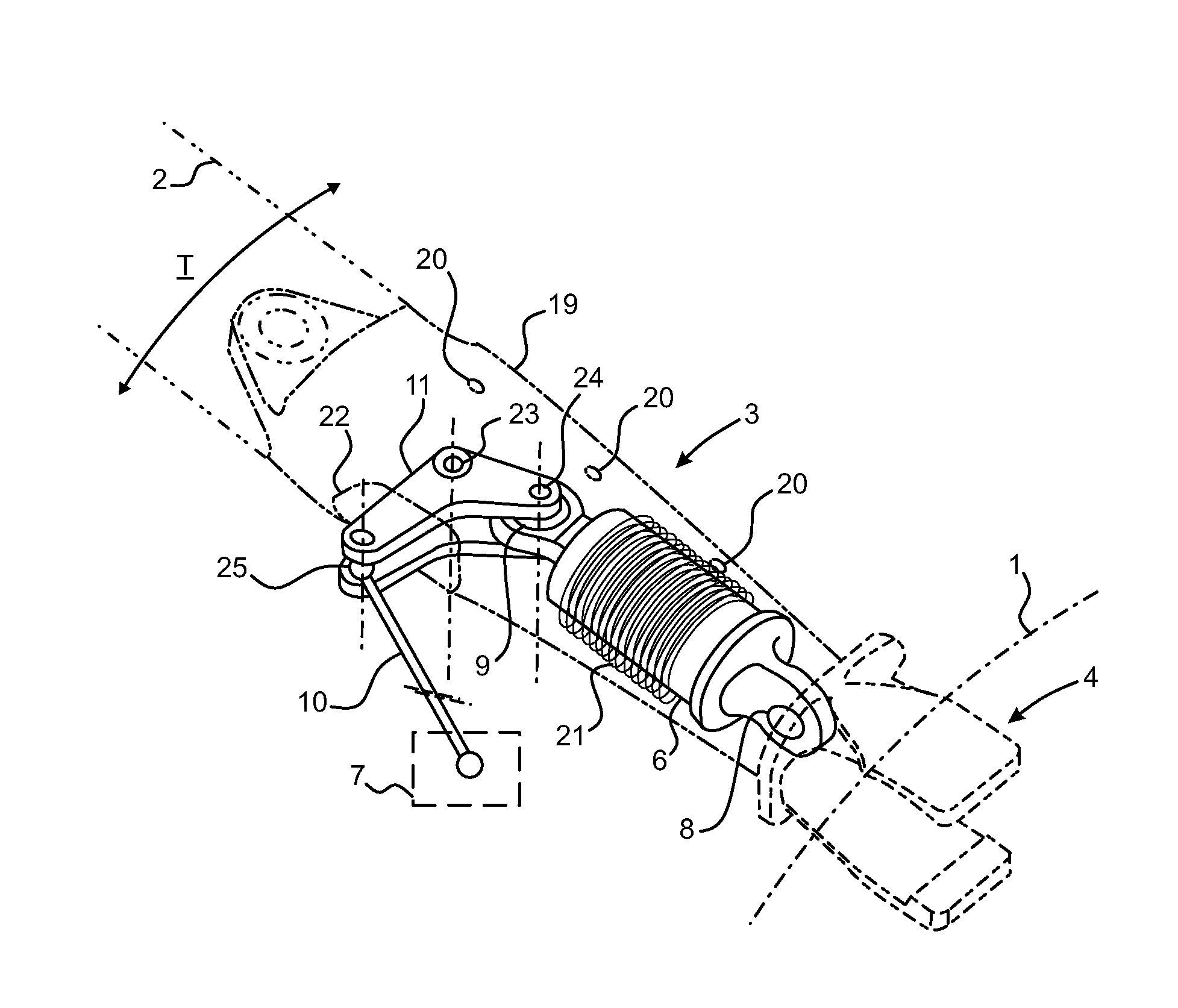
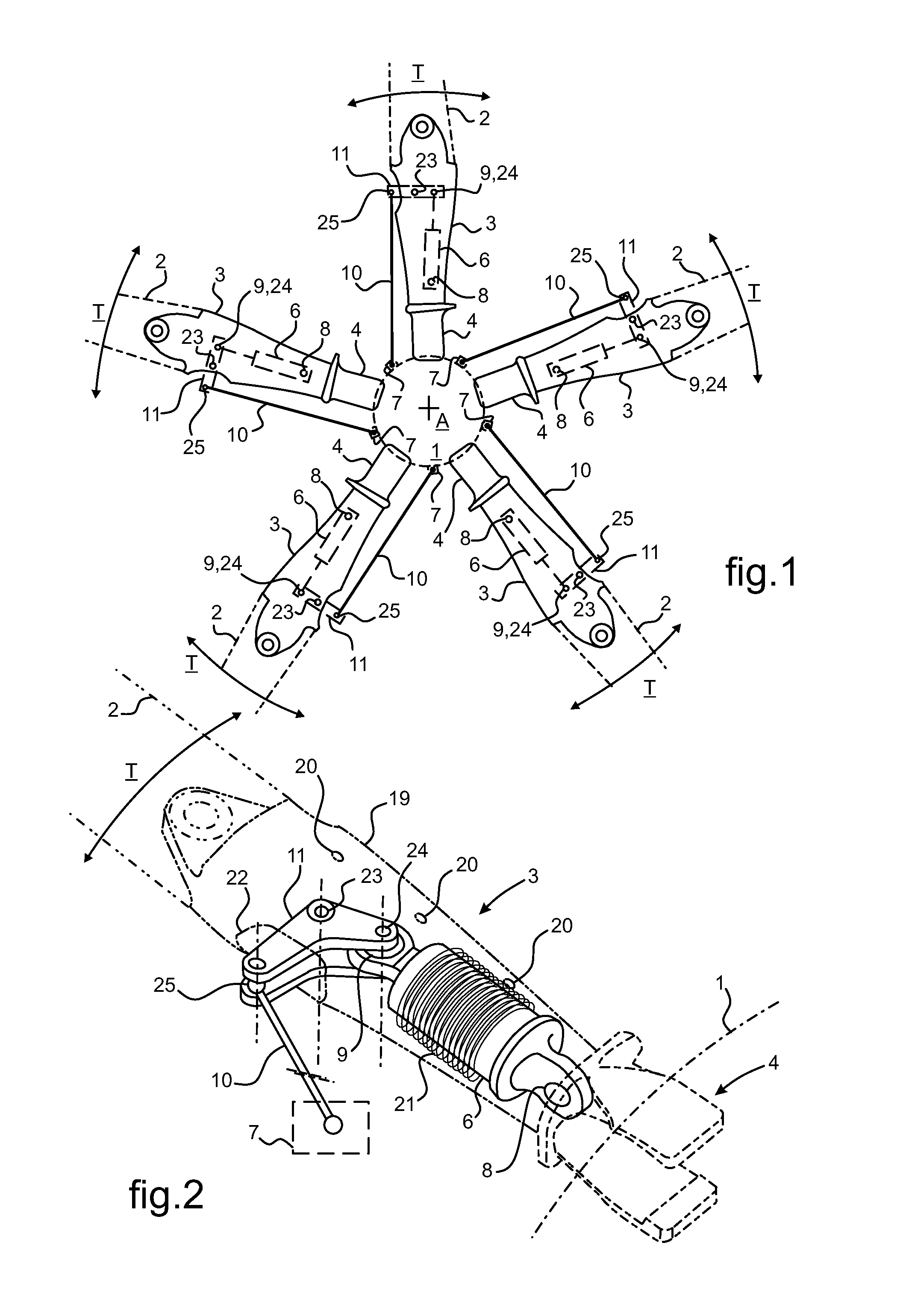
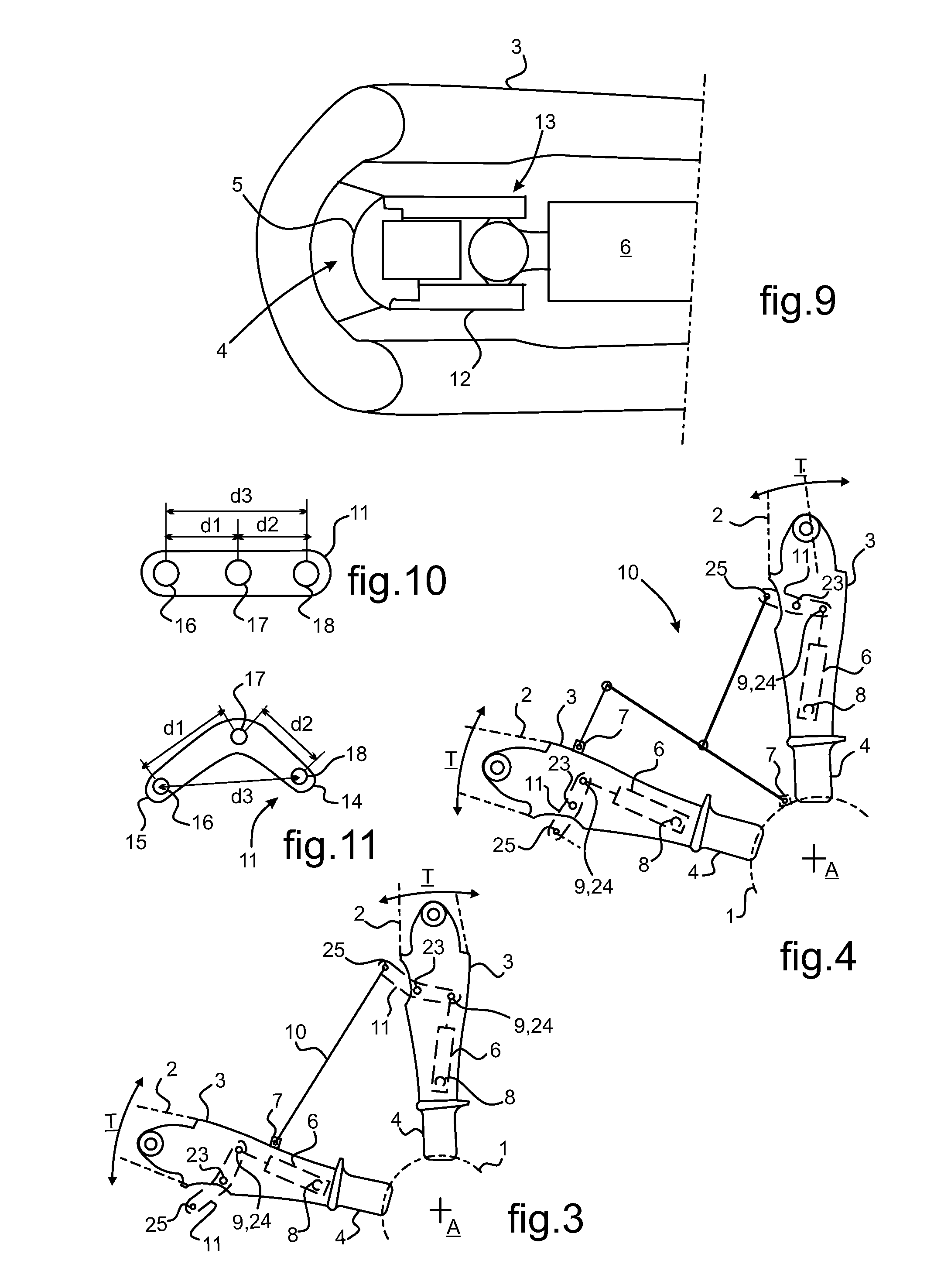
[0076]In FIGS. 1 to 8, a rotorcraft rotor comprises a rotary hub 1 having blades 2 mounted thereon to be driven in rotation. The blades 2 are radially distributed around the hub 1, being assembled to the hub 1 via respective sleeves 3. Each blade is individually carried by a sleeve 3 that is movably mounted on the hub 1 via hinged junction means 4. By way of example, such junction means 4 advantageously involve a spherical abutment member 5 as shown in FIG. 9.

[0077]In the embodiments shown, the blades 2 are secured to the respective sleeves 3 by assembling the blade roots to the sleeves 3. In analogous manner, the blades 2 may be secured to the sleeves 3 by being made integrally therewith.

[0078]While the rotor is in rotation, the blades 2 are subjected to lead-lag oscillations T that need to be damped. Such lead-lag oscillations T take place about respective lead-lag pivot axes of the sleeves relative to the hub. Such a lead-lag pivot axis is substantially parallel to the axis A of ...


PUM


Abstract

A rotorcraft rotor fitted with a device for damping lead-lag oscillations of the blades (2) of the rotor. The blades (2) are hinge-mounted on a rotary hub (1) of the rotor via respective sleeves (3). The damper device comprises a set of dampers (6), each individually housed in a respective one of said sleeves (3) and deformable between two fastening points (8, 9), one with the sleeve and the other with an engagement member (7) for engaging the hub (1) via a linkage (10). For each of the sleeve (3), the damper (6) housed by a given sleeve (3) is in hinged engagement with the linkage (10) via a lever arm (11) hinged to the sleeve (3).

Description

CROSS REFERENCE TO RELATED APPLICATIONS[0001]This application claims priority to French patent application No. FR 12 01986 filed on Jul. 12, 2012, the disclosure of which is incorporated in its entirety by reference herein.BACKGROUND OF THE INVENTION[0002](1) Field of the Invention[0003]The present invention relates to the field of rotorcraft rotors, and it relates more particularly to devices for damping the movements of blades fitted to such rotors.[0004]The present invention provides a device for damping lead-lag oscillations of the blades of a rotorcraft rotor. More specifically, the present invention relates to ways of mounting a damper included in such a damper device on a hub of the rotor.[0005](2) Description of Related Art[0006]Rotorcraft are aircraft with a rotary wing, with this classification including helicopters. A helicopter comprises in particular at least one main rotor with a substantially vertical axis that provides the rotorcraft in flight with lift, with propuls...

Claims


Application Information

Patent Timeline
IPC IPC(8): B64C27/51
CPCB64C27/51B64C27/35B64C27/48B64C27/54B64C27/001B64C27/635
Inventor AMARI, ANDREGAFFIERO, JACQUES
Owner EUROCOPTER
Why Eureka
Try Eureka