Gas pressurized separation column and process to generate a high pressure product gas

Active Publication Date: 2014-01-16
CARBON CAPTURE SCI
View PDF4 Cites 12 Cited by
  • Summary
  • Abstract
  • Description
  • Claims
  • Application Information

AI Technical Summary

Benefits of technology

[0041]It is believed that the process can reduce the energy requirement in the stripping column an

Problems solved by technology

CO2 capture from utility flue gas is the most expensive step in an integrated carbon capture and sequestration (CCS) process.
A conventional absorption/stripping process is energy intensive.
There are several fundamental disadvantages to the conventional stripping processes, including: (a) The operating pressure of the stripper is determined by vapor pressure of the CO2-lean solution in the reboiler, which in turn is determined by composition of lean solution and the

Method used


Image

  • Gas pressurized separation column and process to generate a high pressure product gas
  • Gas pressurized separation column and process to generate a high pressure product gas
  • Gas pressurized separation column and process to generate a high pressure product gas

Examples


Example

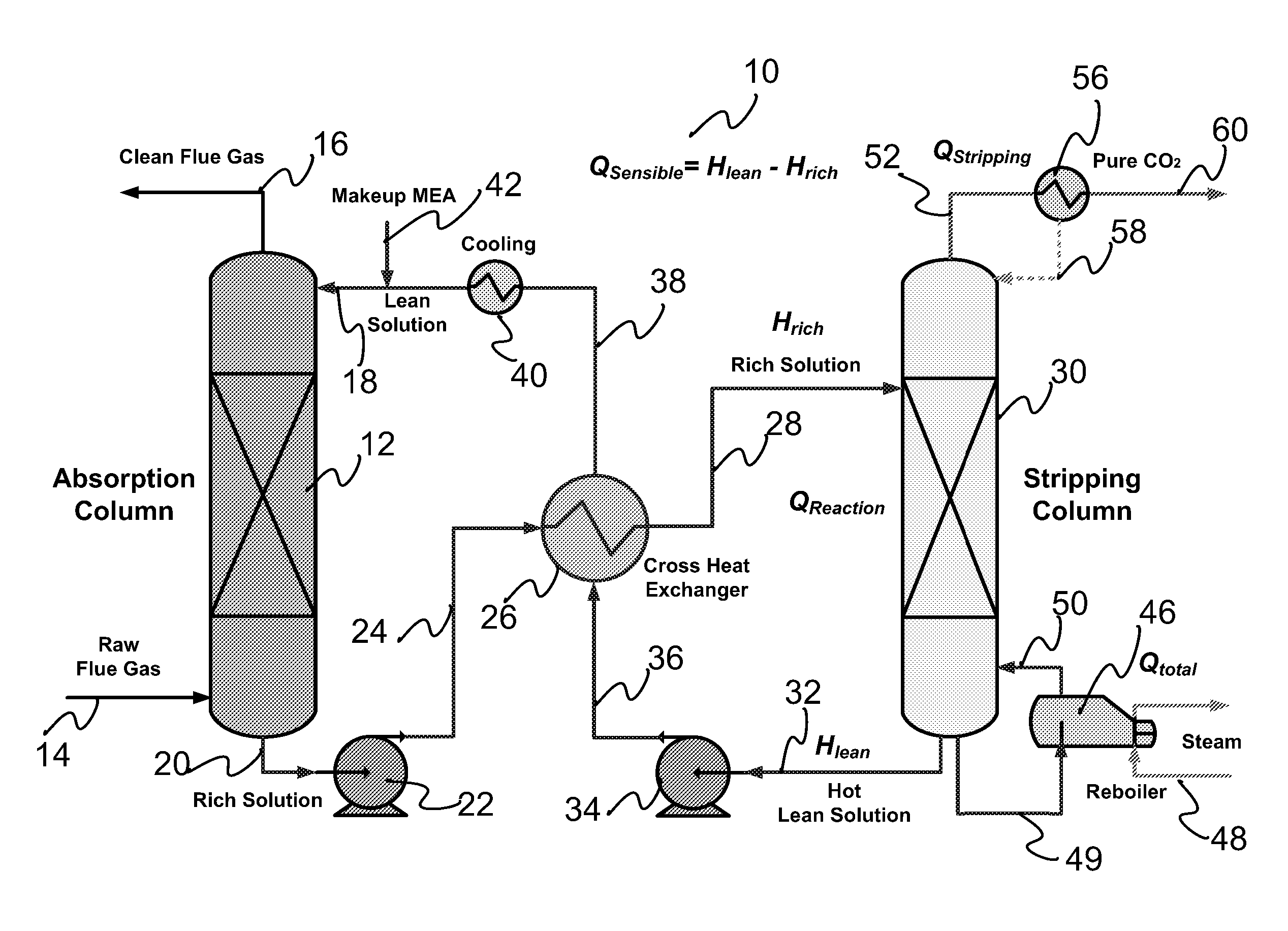
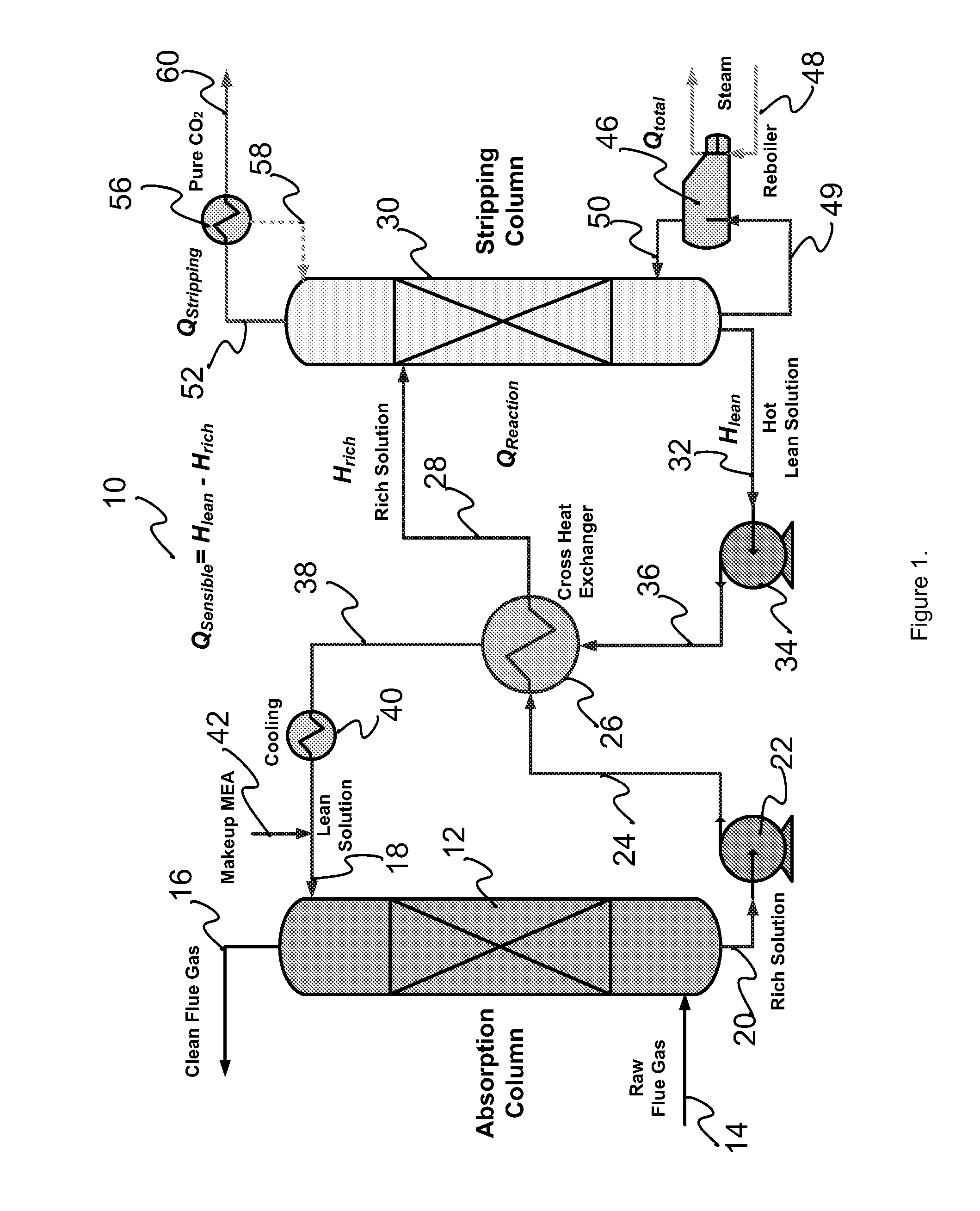
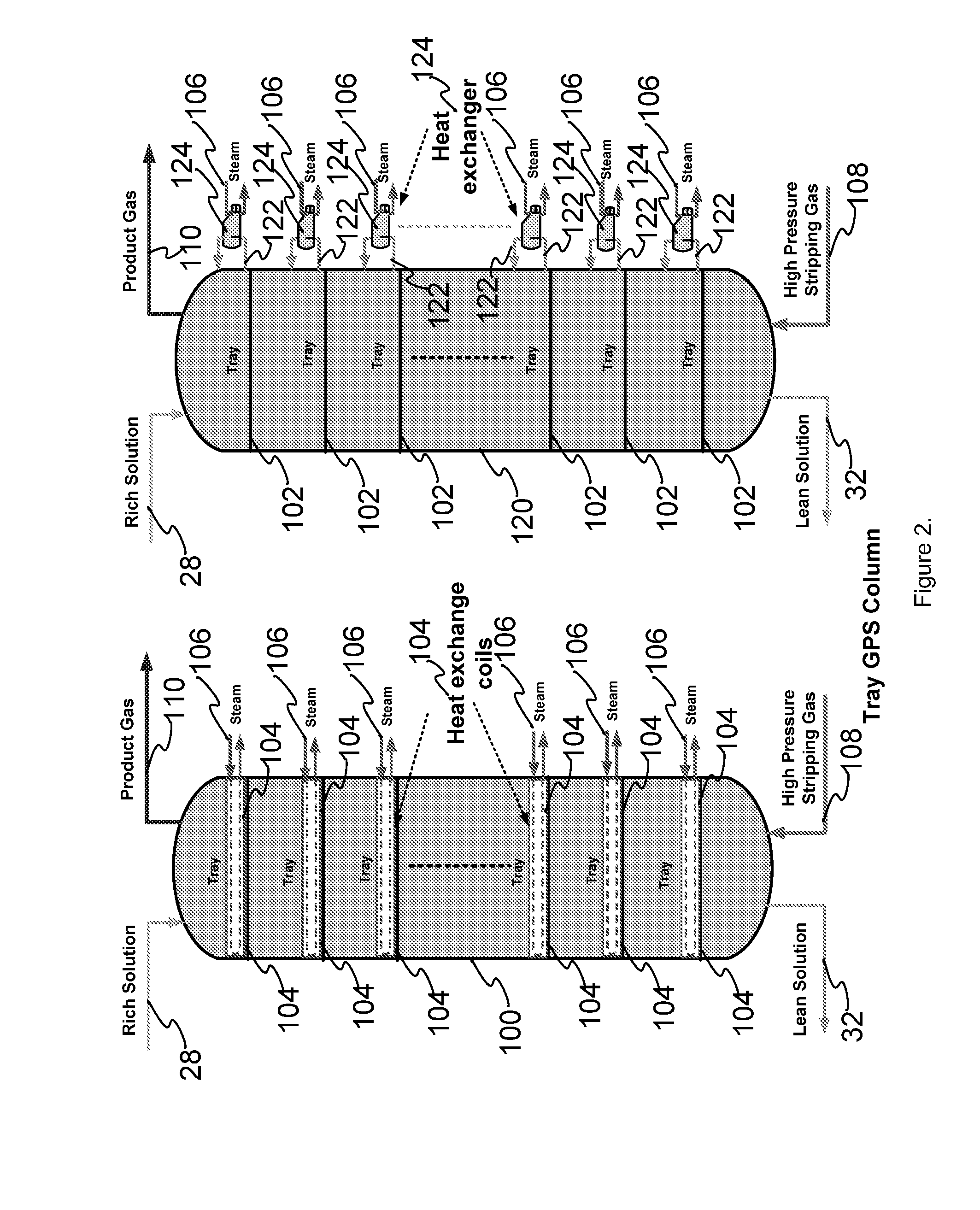
[0054]A gas pressurized separation system of the present invention comprises a gas pressurized stripping column with at least one first inlet allowing flow of one or more liquid streams in a first direction and at least one second inlet allowing flow of one or more high pressure gas streams in a second direction. The directions of each stream within the column may be the same as or different from each other, and may change with respect to each other. For example, they may be co-current (in the same direction) or counter-current (opposite directions) to each other, or anywhere between these two extremes; for example, perpendicular to each other. Also, contact between the streams may include intimate and / or turbulent mixing of the streams.

[0055]The separation column may further comprise two or more heat supplying apparatus, such as heat exchangers or heating coils, positioned in different locations along the column. The heat supplying apparatuses may be connected to each other, such a...


PUM

PropertyMeasurementUnit
Timeaaaaaaaaaa
Pressureaaaaaaaaaa
Temperatureaaaaaaaaaa

Abstract

The present invention provides a gas pressurized separation system to strip a product gas from a liquid stream and yield a high pressure gaseous effluent containing the product gas. The system comprises a gas pressurized stripping apparatus, such as a column, with at least one first inlet allowing flow of one or more liquid streams in a first direction and at least one second inlet allowing flow of one or more high pressure gas streams in a second direction, to strip the product gas into the high pressure gas stream and yield through at least one outlet a high pressure gaseous effluent containing the product gas; and two or more heat supplying apparatuses provided at different locations along the column. Processes for separating a product gas from a gaseous mixture to yield a high pressure gaseous effluent containing the product gas, utilize the gas pressurized separation system described above.

Description

RELATED APPLICATIONS[0001]This application is a Continuation in Part of U.S. patent application Ser. No. 12 / 833,906, filed Jul. 9, 2010 entitled “A Gas Pressurized Separation Column and Process to Generate a High Pressure Product Gas.” U.S. patent application Ser. No. 12 / 833,906 published as U.S. Publication 2012-0009114 on Jan. 12, 2012, which publication is incorporated herein by reference.[0002]This application is a Continuation in Part of International Patent Application serial number PCT / US11 / 43485, filed Jul. 11, 2011 entitled “A Gas Pressurized Separation Column and Process to Generate a High Pressure Product Gas.” International Patent Application serial number PCT / US11 / 43485 was published as Publication WO 2012 006610 on Jan. 12, 2012, which publication is incorporated herein by reference.FIELD OF THE INVENTION[0003]The present invention relates to gas pressurized separation columns and to processes utilizing the columns.BACKGROUND OF THE INVENTION[0004]CO2 capture from util...

Claims


Application Information

Patent Timeline
IPC IPC(8): B01D53/14
CPCB01D53/1425B01D19/0005B01D19/0015C01B32/50B01D53/1475B01D2258/0283B01D2252/20484B01D2252/20489B01D2252/20426Y02C20/40Y02P20/151
Inventor CHEN, SHIAOGUOPAN, ZIJIANG
Owner CARBON CAPTURE SCI
Why Eureka
Try Eureka