
Eureka
For R&D, Eureka makes reading and utilizing patents & technical documents easy.
Eureka AIR
Designed for self-driven R&D workflows. Generate viable solutions, solve complex R&D challenges, empower your innovation with AI.

Eureka Materials
Designed for material experts only. Revolutionize your material R&D, from search, analyze, to developing new materials.

TechResearch
Generate reliable direction feasibility study reports for your R&D in just a few steps.

TechSeek
Discover and master advanced knowledge NOW. Basics, ideas, possibilities, all at once.

TechMind
As an expert in R&D Theories, TechMind can generates customized viable solutions instantly.

TechRisk
Analyze your overall solution with one click, know your potential R&D risks in advance.

TechMonitor
Get weekly tech updates, stay abreast of the latest tech innovations and key insights.
Measurement system for measuring inductance
- Summary
- Abstract
- Description
- Claims
- Application Information
AI Technical Summary
Benefits of technology
Problems solved by technology
Method used
Image

Examples
Embodiment Construction
[0010]The disclosure, including the drawing, is illustrated by way of example and not by way of limitation. References to “an” or “one” embodiment in this disclosure are not necessarily to the same embodiment, and such references mean at least one.
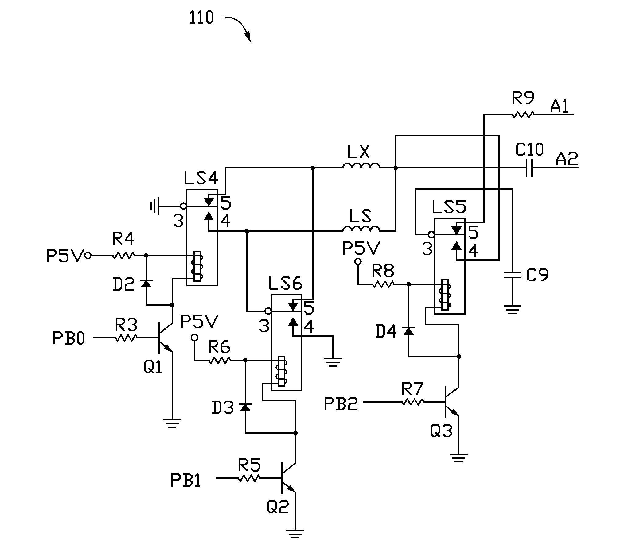
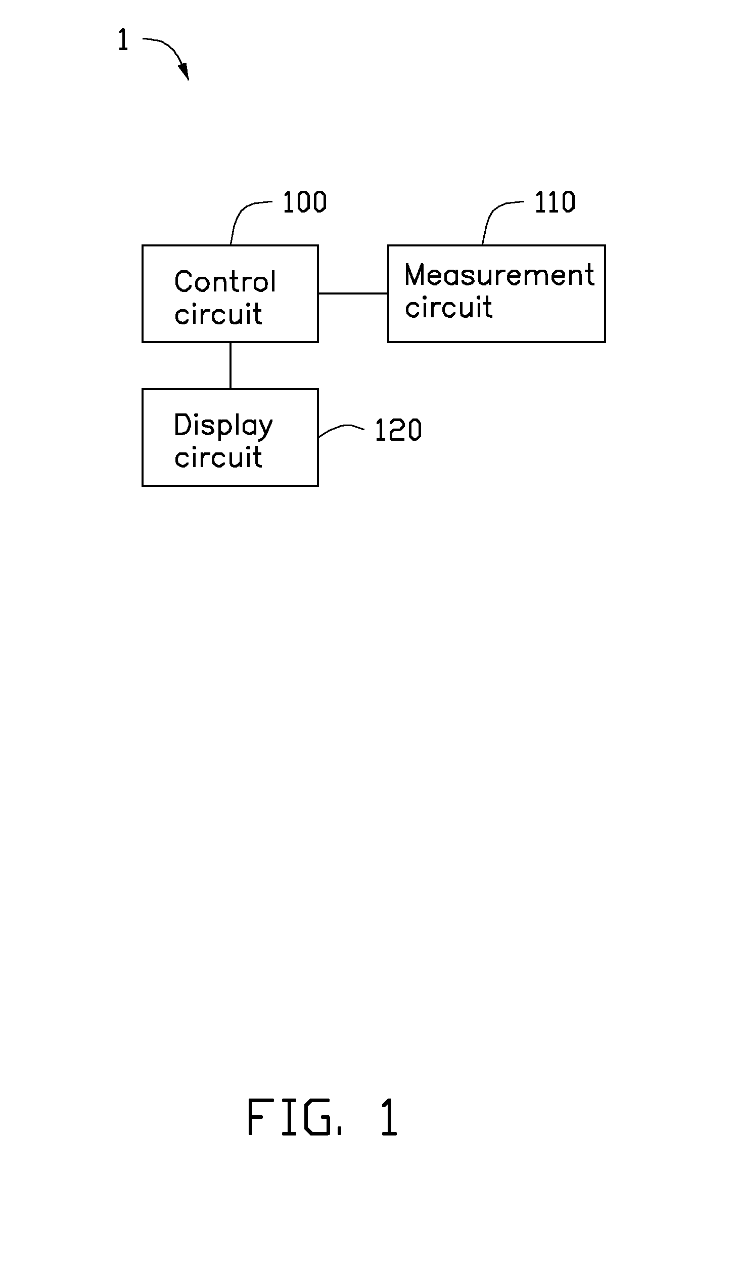
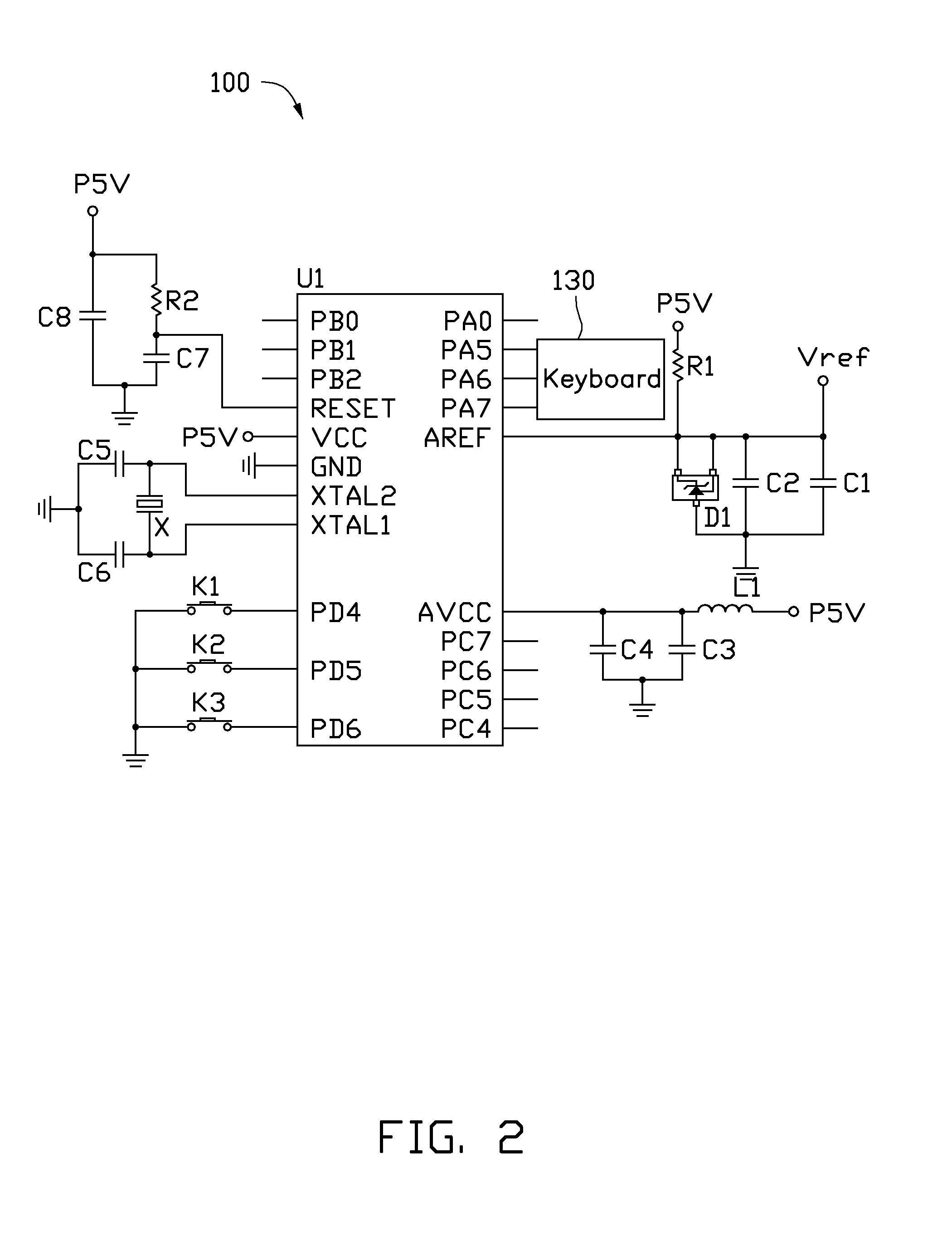
[0011]Referring to FIGS. 1 and 3, a measurement system 1 in accordance to an exemplary embodiment is shown. The measuring system 1 is used for measuring inductance of first and second inductors Ls and Lx. The measurement system 1 includes a control circuit 100, a measurement circuit 110, and a display circuit 120. The measurement circuit 110 comprises a capacitor C9.
[0012]The control circuit 100 is connected to the measurement circuit 110, to control the first inductor Ls or the second inductor Lx and the capacitor C9 to compose an LC circuit. The control circuit 100 receives a frequency from the LC circuit, to gain the inductance L according to a formula:
L=14π·f2·C9,
where L stands for inductance of the first inductor Ls or the second indu...
PUM
 Abstract
Description
Claims
Application Information
 - R&D Engineer
- R&D Manager
- IP Professional
- Industry Leading Data Capabilities
- Powerful AI technology
- Patent DNA Extraction
Browse by: Latest US Patents, China's latest patents, Technical Efficacy Thesaurus, Application Domain, Technology Topic, Popular Technical Reports.
© 2024 PatSnap. All rights reserved.Legal|Privacy policy|Modern Slavery Act Transparency Statement|Sitemap|About US| Contact US: help@patsnap.com