Apparatus for using cast-off heat to warm water from household water heater

a technology for transferring heat and water heaters, which is applied in the direction of heating types, domestic hot water supply systems, and steam generation using hot heat carriers, etc. it can solve the problems of not having an existing pump or heating system, water heaters that do not disclose the arrangement of domestic hot water heaters and air conditioners, and achieve no additional energy costs, the effect of lowering the cost of running the air conditioner and lowering the cost of heating water

Inactive Publication Date: 2014-01-23
YAMIN OFIR
View PDF11 Cites 20 Cited by
  • Summary
  • Abstract
  • Description
  • Claims
  • Application Information

AI Technical Summary

Benefits of technology

[0007]The innovative retrofit heat transfer system of the immediate innovation uses heat produced by an air conditioner compressor to heat the water in a (household) water heater. When refrigerant gas is compressed back into a liquid the line holding the liquid gets very hot (75° C.-85° C.). This heat must be released for the liquid to cool. The refrigerant runs through a coaxial coil heat-exchanger or a plate heat-exchanger in order to cool the refrigerant liquid, which then continues to travel through the condensation coils for continued working. When the air conditioner is active then refrigerant liquid flows through the heat exchanger while cool water is pumped from the water heater—by a water pump—through the heat exchanger, thereby bringing the cool water into contact with the hot refrigerant fluid line. The hot fluid line can have an average temperature of 80° C. The pu...

Problems solved by technology

The '833 application fails to disclose a domestic water heater-air conditioner arrangement.
A water heater, on the other hand, does not have an existing pump or heati...

Method used


Image

  • Apparatus for using cast-off heat to warm water from household water heater
  • Apparatus for using cast-off heat to warm water from household water heater
  • Apparatus for using cast-off heat to warm water from household water heater

Examples


Embodiment Construction

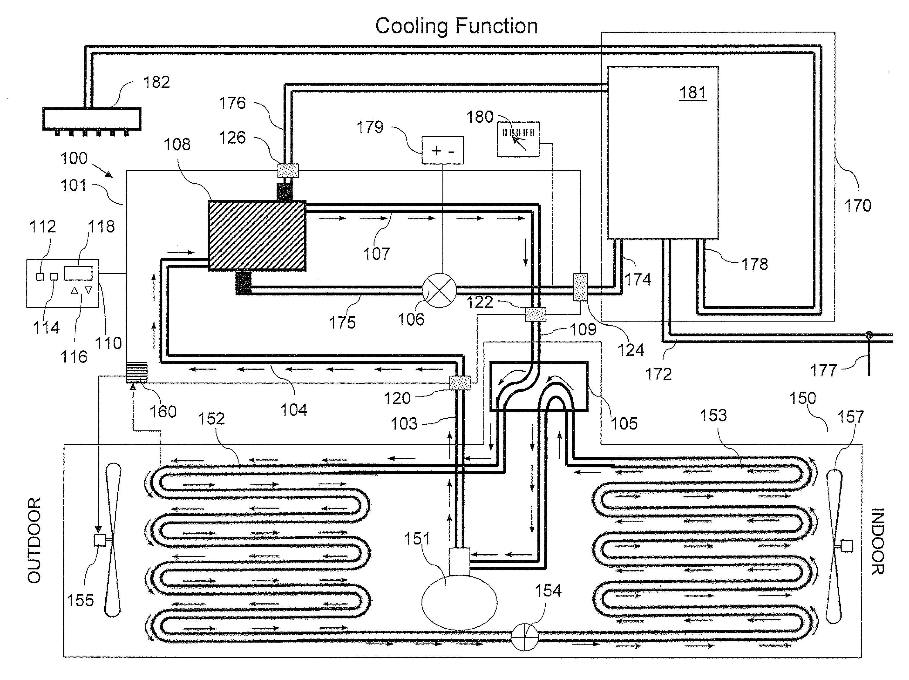
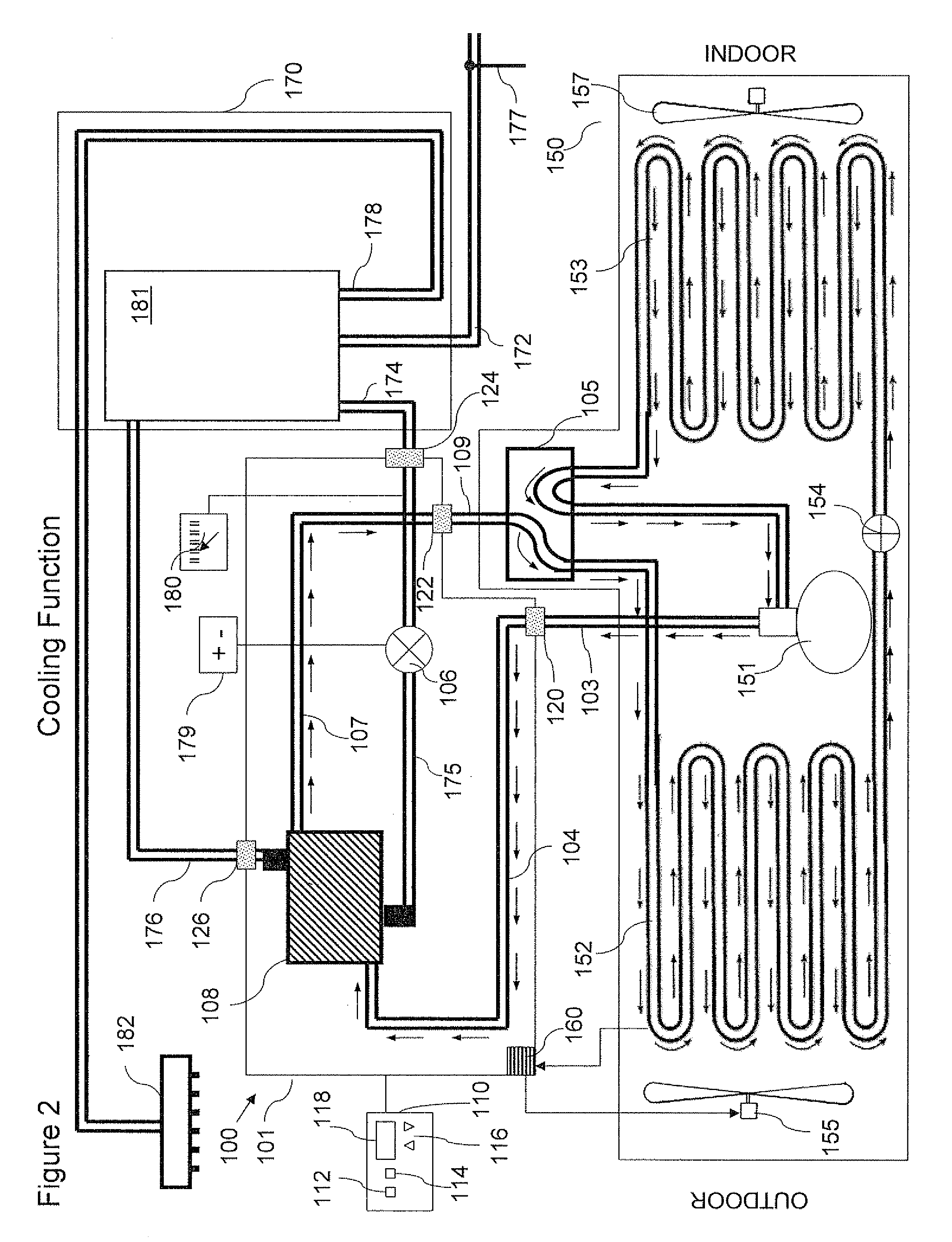
[0028]The principles and operation of a retrofit heat transfer system according to the present invention may be better understood with reference to the drawings and the accompanying description.

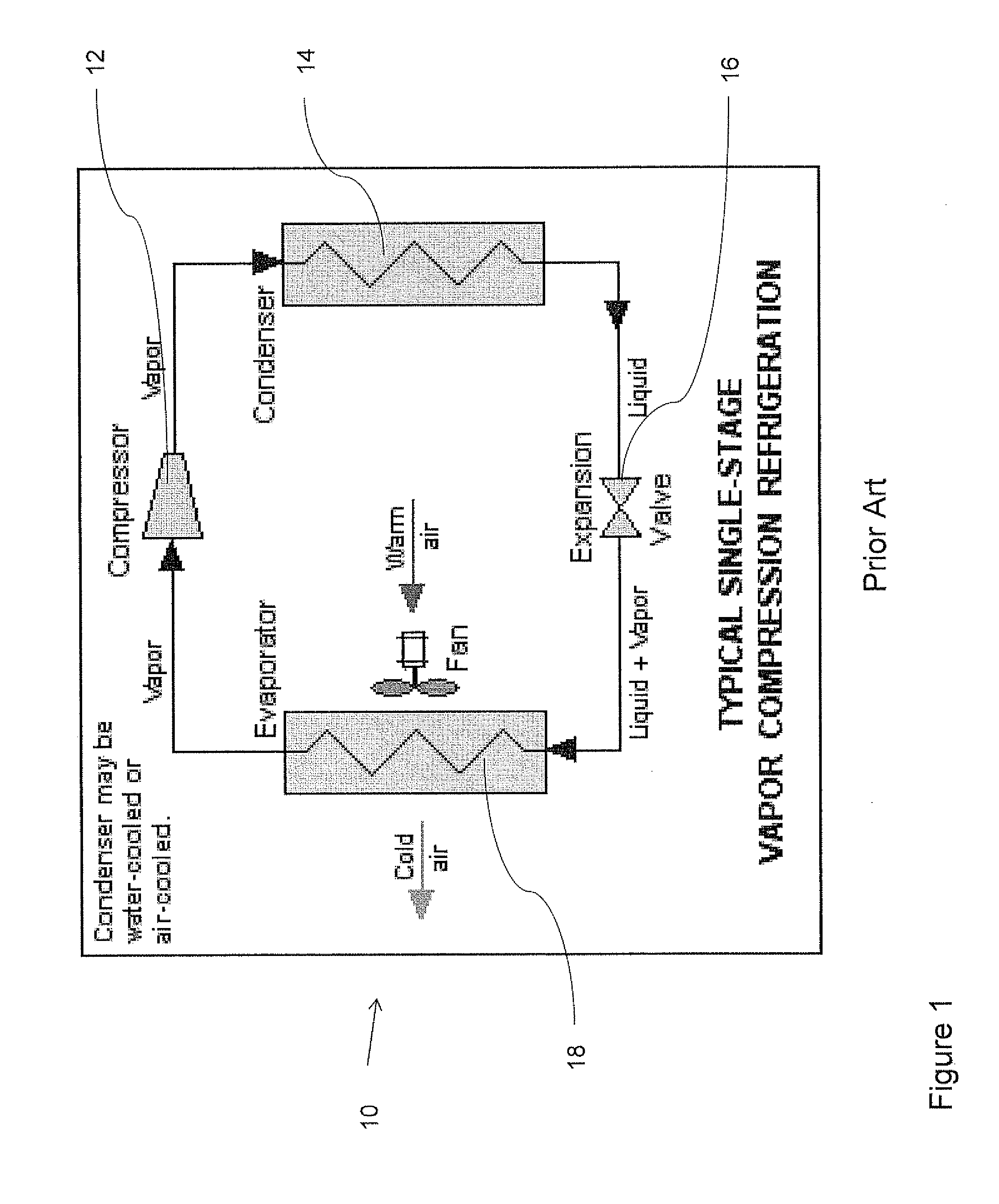
[0029]Referring now to the drawings, FIG. 1 is a typical vapor compression refrigeration system known in the art. The vapor-compression uses a circulating liquid refrigerant as the medium which absorbs and removes heat from the space to be cooled and subsequently rejects that heat elsewhere. FIG. 1 depicts a typical, single-stage vapor-compression system. All such systems have the following four components: a compressor 12, a condenser 14, a Thermal expansion valve 16, and an evaporator 18. Circulating refrigerant enters compressor 12 in the thermodynamic state known as a saturated vapor (i.e. gaseous state) and is compressed to a higher pressure, resulting in a higher temperature as well. The hot, compressed vapor is then in the thermodynamic state known as a superheated vapor and it is at a...


PUM

PropertyMeasurementUnit
Temperatureaaaaaaaaaa
Pressureaaaaaaaaaa

Abstract

A retrofit heat transfer unit, including: a housing for the retrofit unit, including inlet and outlet ports for water and refrigerant; a water pump, in fluid communication with the water inlet port, the water pump adapted to pump water from a water source; a heat exchanger, in fluid communication with the water pump, the water outlet port, the refrigerant inlet port and the refrigerant outlet port; and a thermostat, configured to measure a temperature of the pumped water and activate the water pump when the water is below a predefined low temperature and cease to pump when water is above a predefined high temperature. The retrofit unit is also adapted to receive heated refrigerant fluid from an air conditioner and direct the refrigerant through the heat exchanger and direct the pumped water into the heat exchanger so that the refrigerant heats the water and the water cools the refrigerant.

Description

FIELD AND BACKGROUND OF THE INVENTION[0001]The present invention relates to a heat transfer apparatus and, more particularly, to an apparatus for transferring heat from an air conditioner unit to water from a water heater.[0002]A legacy air conditioner uses refrigerant to cool down a space. The refrigerant (e.g. Freon) cools to very low temperatures which is useful in cooling an indoor space. A fan blows air over Evaporator coils (coils which contain cool refrigerant) to cool the room. Another characteristic of the refrigerant used in air conditioners is that it absorbs heat from the air in the room and returns cooled air. The absorbed heat must be released though, and this is the job of the Condenser. Condenser coils are usually located outdoors and have a fan which blows air over the coils (which contain very hot refrigerant, often between 70° C. and 80° C.). The fan air cools the coils and refrigerant so that the refrigerant can be reused to cool the indoor space. In some systems...

Claims


Application Information

Patent Timeline
IPC IPC(8): F22B1/02B21D53/02
CPCF24D15/04F24D17/02F24D2200/04F24H4/02F24H6/00F24D19/1054F24D19/1087F24D2200/123F24F5/0096F25B6/04F25B13/00F25B2313/021Y10T29/4935
Inventor YAMIN, OFIR
Owner YAMIN OFIR
Why Eureka
Try Eureka