
Luminescent converter for a phosphor enhanced light source

a technology of phosphor enhanced light and converter, which is applied in the direction of discharge tube luminescnet screen, discharge tube/lamp details, natural mineral layered products, etc., can solve the problems of difficult light creation and relatively high color rending

Pending Publication Date: 2014-01-23
KONINKLIJKE PHILIPS ELECTRONICS NV
View PDF2 Cites 9 Cited by
  • Summary
  • Abstract
  • Description
  • Claims
  • Application Information

AI Technical Summary

Benefits of technology

The patent describes a way to create a luminescent converter that emits light in a wide range of color ranges, resulting in a high color rending index. This is achieved by adding a third luminescent material that emits a different color, which compensates for the self-absorption of the first and second materials. The use of inorganic material is stable and cost-effective, and the luminaire provides the same benefits as the luminescent converter or phosphor-enhanced light source.

Problems solved by technology

However, as discussed previously, it is difficult to create light which has a relatively high color rending index (CRI), for example, larger than 80.

Method used


Image

  • Luminescent converter for a phosphor enhanced light source
  • Luminescent converter for a phosphor enhanced light source
  • Luminescent converter for a phosphor enhanced light source

Examples


Embodiment Construction

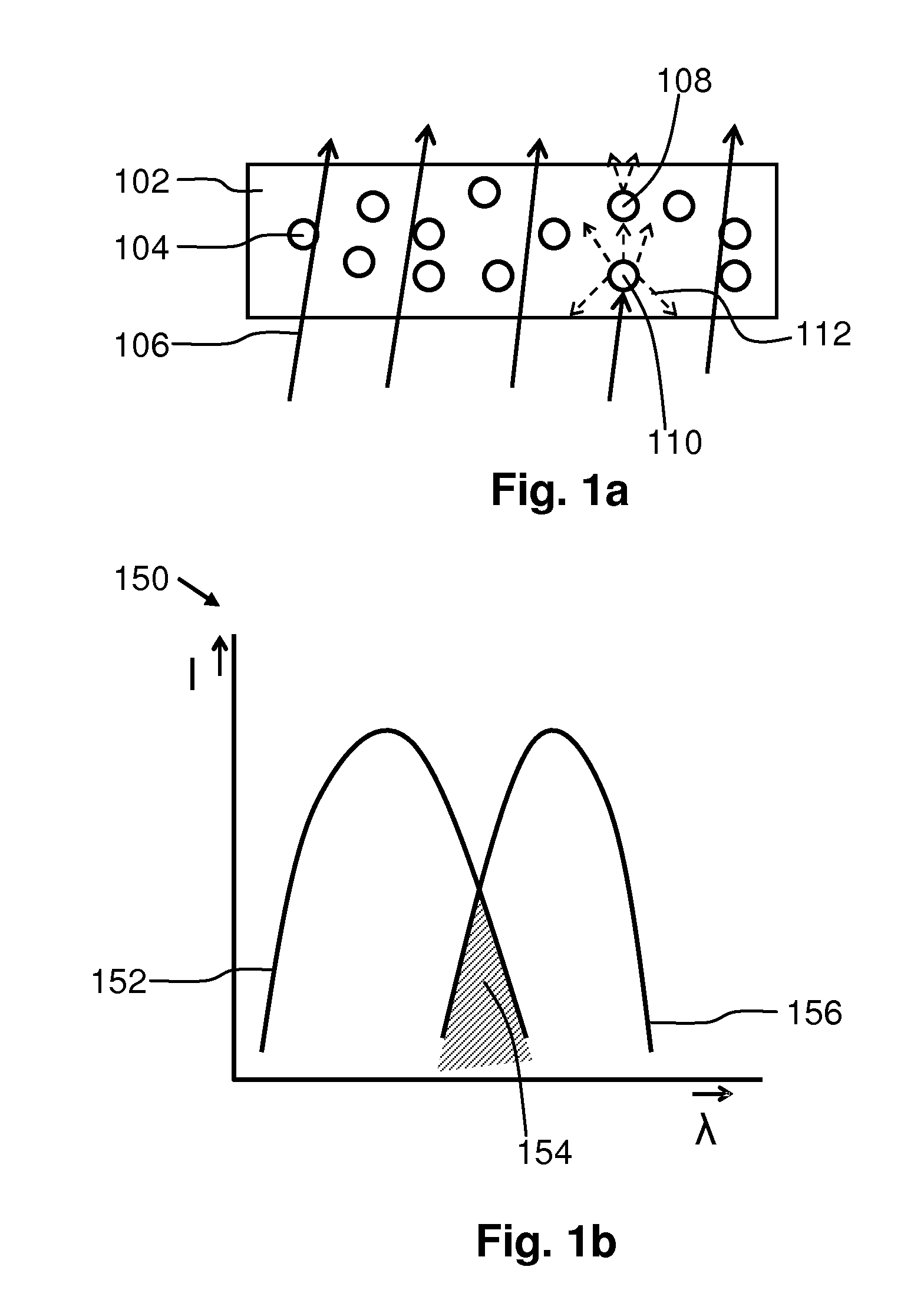
[0057]FIGS. 1a and 1b schematically present the phenomena of self-absorption. In FIG. 1a a layer 102 of a matrix polymer is presented which comprises luminescent molecules 104, 108, 110. The size of the luminescent molecules 104, 108, 110 is exaggerated strongly for clarity reasons. The luminescent molecules 104, 108, 110 are of an organic luminescent material. The layer 102, which comprises the luminescent molecules 104, 108, 110, has good light transmission characteristics because the matrix polymer is transparent and does not show absorption of light. Further, the organic luminescent material is relatively transparent. Consequently, only the wavelengths falling within the absorption spectral range of the luminescent material are absorbed by the layer. Light 106 of a predefined color distribution impinges on one side of the layer 102. A portion of the light 106 is transmitted through the layer 102. Another portion of the light 106 is absorbed by the luminescent molecules 110.

[0058...


PUM

PropertyMeasurementUnit
color rendering indexaaaaaaaaaa
CRIaaaaaaaaaa
thicknessaaaaaaaaaa

Abstract

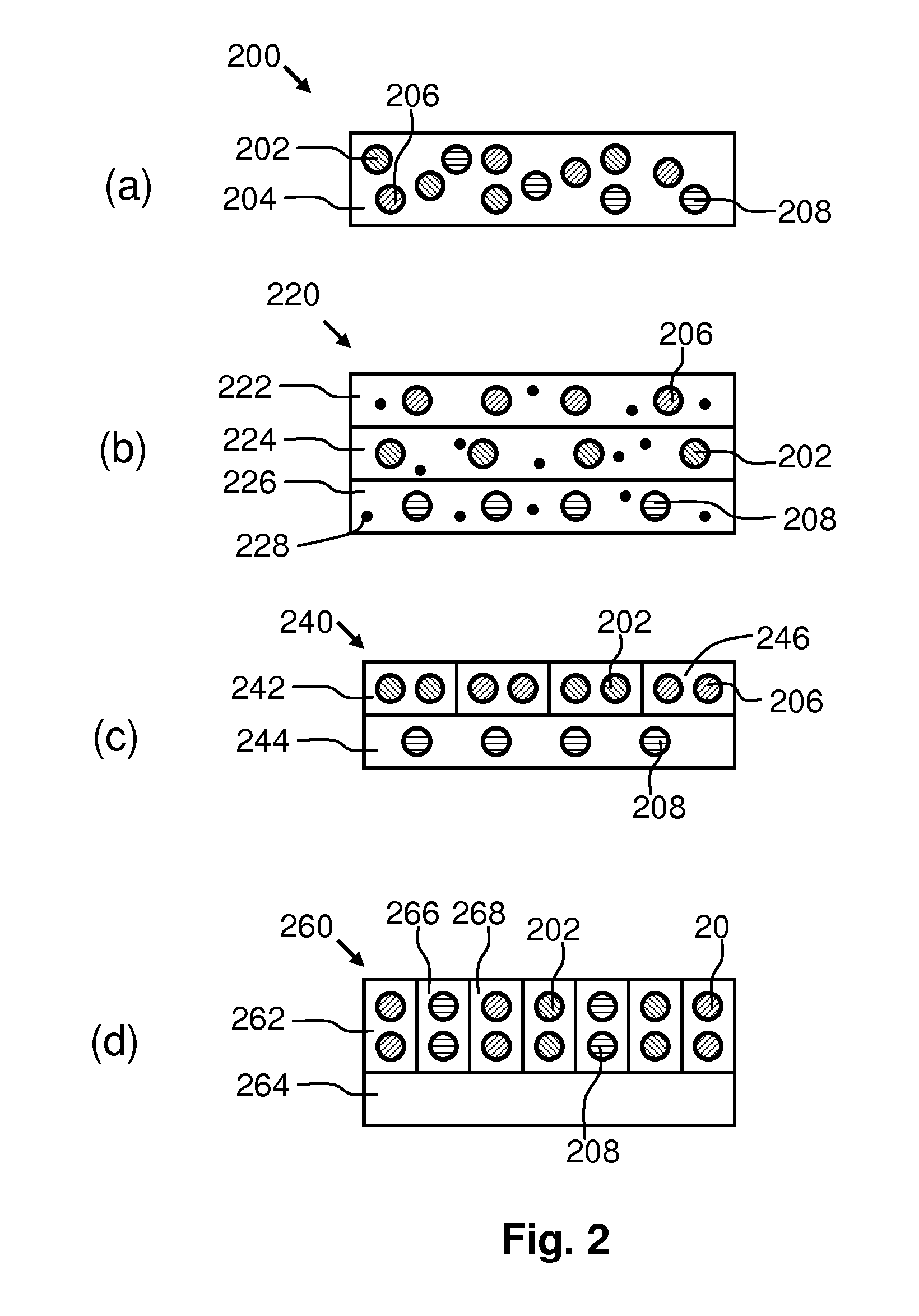
A luminescent converter 200, 220, 240, 260, a phosphor-enhanced light source and a luminaire are provided. The luminescent converter 200 comprises a first organic luminescent material 202, a second organic luminescent material 208 and a third inorganic luminescent material 206. The first organic luminescent material 202, the second organic luminescent material 208 and the inorganic luminescent material 206 absorb a portion of light emitted by the light source and / or absorbs a portion of light emitted by at least one of the other luminescent materials. The first organic luminescent material 202 converts at least a part of the absorbed light into light of a first color distribution. The second organic luminescent material 208 converts at least a part of the absorbed light into light of a second color distribution. The inorganic luminescent material 206 converts at least a part of the absorbed light into a third color distribution to compensate self-absorption of light by at least one of the first organic luminescent material 202 and the second organic luminescent material 208.

Description

FIELD OF THE INVENTION[0001]The invention relates to luminescent product for converting light of a first color distribution to light of another color distribution.BACKGROUND OF THE INVENTION[0002]In many applications luminescent material is combined with a solid state light emitter to generate a light emission distribution which is experienced by users as white light. The color rendering index of the light emission distribution of the generated white light should be relatively high to have a good color rending index.[0003]It is known to combine different inorganic luminescent materials that each emits light of a different color together with a solid state light emitter which emits light of a single color. Inorganic luminescent materials are stable and may be used at a relatively high temperature. However, inorganic luminescent materials are relatively expensive.[0004]In order to reduce costs, in some applications so-termed remote organic phosphors are used, which are mixes of organi...

Claims


Application Information

Patent Timeline
Patent Type & Authority Applications(United States)
IPC IPC(8): C09K11/06H05B33/12
CPCC09K11/06H05B33/12C09K11/7774C09K2211/1011C09K2211/1029C09K2211/1044H01L33/504
Inventor VAN BOMMEL, TIESHIKMET, RIFAT ATA MUSTAFAKRIEGE, JAN CORNELIS
Owner KONINKLIJKE PHILIPS ELECTRONICS NV
Learn More