
Delay locked loop circuit and method of driving the same

a technology of delay lock and loop circuit, which is applied in the direction of digital storage, pulse automatic control, instruments, etc., can solve the problems of delay lock operation not being completed, output data not being synchronized with an external system dock, external devices not receiving data properly from a semiconductor memory device,

Active Publication Date: 2014-01-23
SK HYNIX INC
View PDF1 Cites 25 Cited by
  • Summary
  • Abstract
  • Description
  • Claims
  • Application Information

AI Technical Summary

Benefits of technology

The present invention provides a DLL that can detect delay locking without errors and prevent half phase locking failures and phase locking misses. This improves the reliability and accuracy of the semiconductor device's delay locking process.

Problems solved by technology

If the locking detector determines that a delay locked operation has been completed even when the delay locked operation has not been completed, and thus, activates a locking detection signal, the semiconductor memory device erroneously detects that the delay locked operation has been completed and outputs data externally.
Furthermore, a delay locked operation may not be completed because a locking detection signal is not activated when the delay locked operation is completed.
Even in this case, the output data may not be synchronized with an external system dock.
As a result, an external device may not properly receive data outputted from a semiconductor memory device,

Method used


Image

  • Delay locked loop circuit and method of driving the same
  • Delay locked loop circuit and method of driving the same
  • Delay locked loop circuit and method of driving the same

Examples


Embodiment Construction

[0031]Exemplary embodiments of the present invention will be described below in more detail with reference to the accompanying drawings. The present invention may, however, be embodied in different forms and should not be construed as limited to the embodiments set forth herein. Rather, these embodiments are provided so that this disclosure will be thorough and complete, and will fully convey the scope of the present invention to those skilled in the art. Throughout the disclosure, like reference numerals refer to like parts throughout the various figures and embodiments of the present invention.

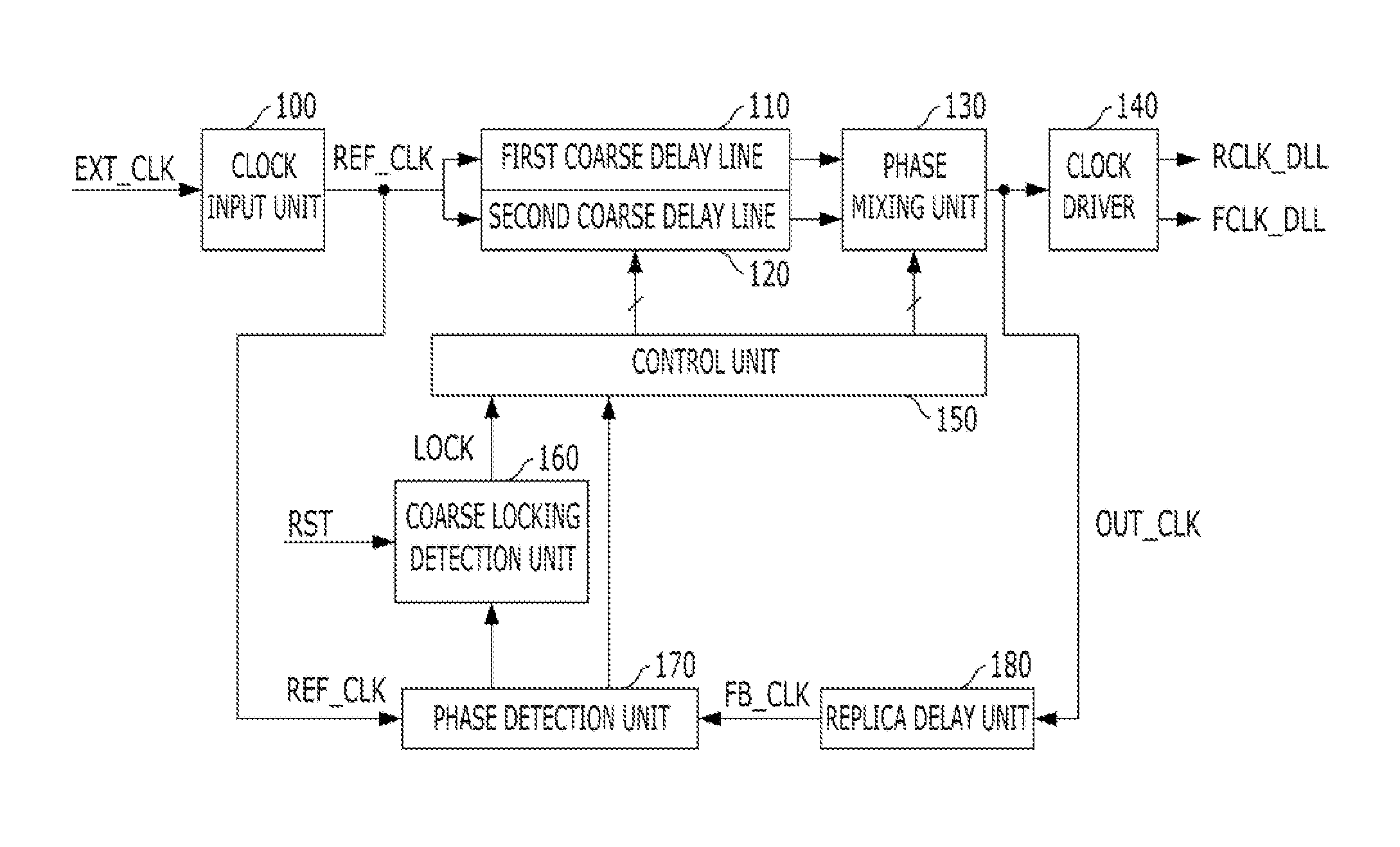
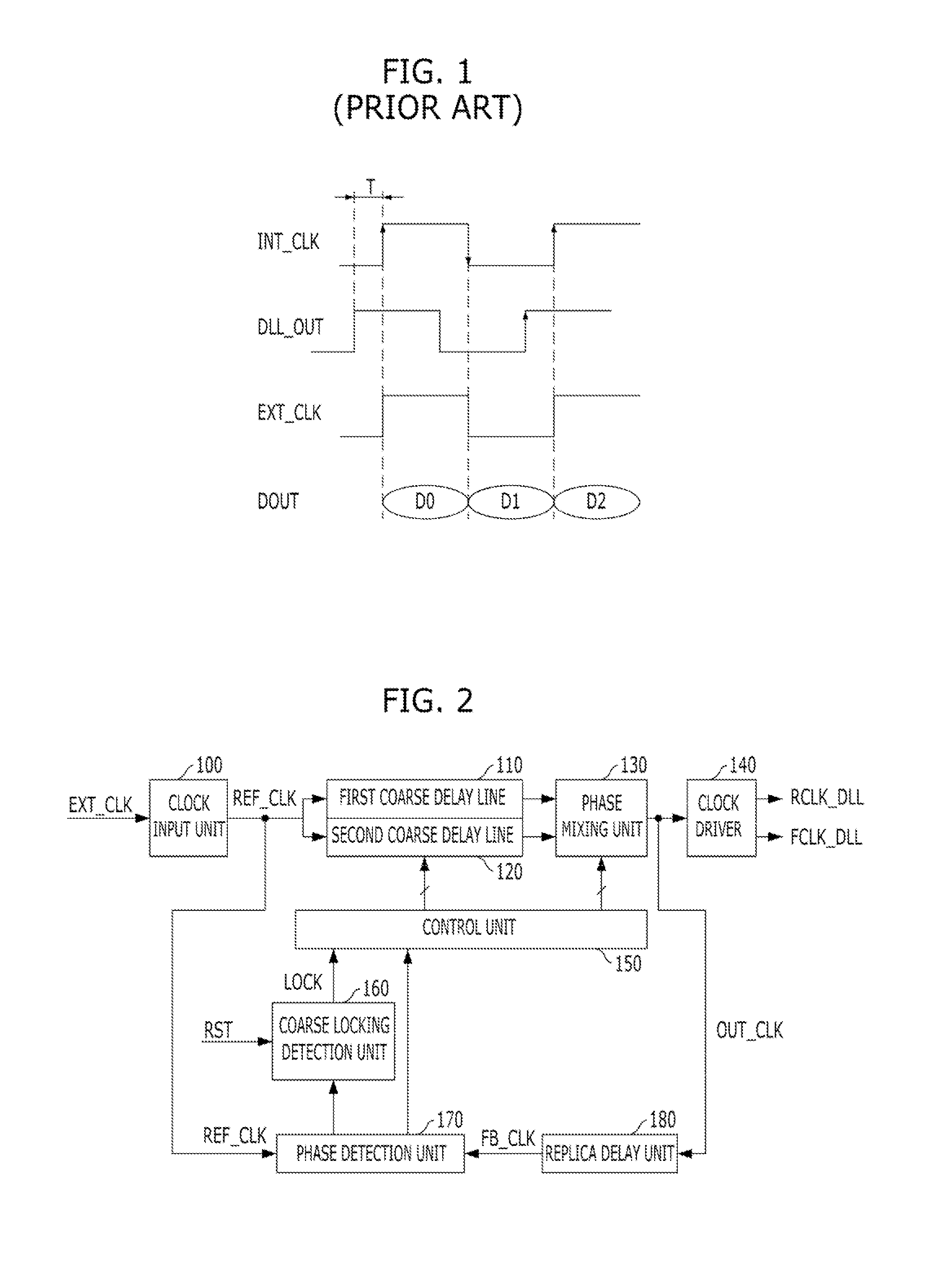
[0032]FIG. 2 is a block diagram of a DLL circuit for illustrating the present invention.

[0033]Referring to FIG. 2, the DLL circuit includes a clock input unit 100 first and second coarse delay lines 110 and 120, a phase mixing unit 130, a clock driver 140, a control unit 150, a coarse locking detection unit 160, a phase detection unit 170, and a replica delay unit 180.

[0034]The clock input u...


PUM


Abstract

The DLL comprises a coarse delay line configured to have a plurality of unit delays and delay an reference dock to output a delayed clock, a fine delay line configured to delay the delayed clock to output a delayed output clock, a replica delay unit configured to delay the delayed output clock by an expected modeling value to output a feedback clock, a phase detection unit configured to compare a phase of the feedback clock with a phase of the reference clock to generate first to third phase detection signals based on a result of the comparison, a locking detection unit configured to output a locking signal by selecting a first locking detection signal or a second locking detection signal, and a control unit configured to control the coarse and fine delay lines in response to the locking signal and the first phase detection signal.

Description

CROSS-REFERENCE TO RELATED APPLICATIONS[0001]The present application claims priority of Korean Patent Application No. 10-2012-0078808, filed on Jul. 19, 2012, which is incorporated herein by reference in its entirety.BACKGROUND[0002]1. Field[0003]Exemplary embodiments of the present invention relate to semiconductor design technology, and more particularly, to a Delay-Locked Loop (DLL) circuit for a semiconductor device and a method of driving the same.[0004]2. Description of the Related Art[0005]In general, a DLL circuit is used to provide a delay locked clock having a phase, which is earlier than the phase of an internal clock by a specific time, obtained by converting an external clock. An internal clock used in a semiconductor integrated circuit is delayed through a clock buffer and transmission lines, and thus, a phase difference occurs between the internal clock and an external clock. A DLL circuit may be used to solve concerns in which the output timing of output data is not ...

Claims


Application Information

Patent Timeline
Patent Type & Authority Applications(United States)
IPC IPC(8): H03L7/10
CPCH03L7/10H03L7/0814H03L7/0816H03L7/0818H03L7/085H03L7/087H03L7/095G11C11/407H03L7/081
Inventor NA, KWANG-JIN
Owner SK HYNIX INC
Learn More