Hairspring for a time piece and hairspring design for concentricity

a timepiece and concentricity technology, applied in the field of new design of a mechanical timepiece hairspring, can solve the problems of increasing manufacturing difficulties and costs, affecting the ability of the oscillator to reliably regulate the time, and difficulty in mass production

Active Publication Date: 2014-01-23
MASTER DYNAMIC LTD
View PDF8 Cites 12 Cited by
  • Summary
  • Abstract
  • Description
  • Claims
  • Application Information

AI Technical Summary

Benefits of technology

[0086]The present invention allows substantially complete thermo-compensation of a silicon hairspring with a silicon dioxide coating because each side-by-side branch of a multi-strip spiral section can maintain the same width as the other branches of the other spiral sections.
[0087]The present invention all

Problems solved by technology

As the balance wheel rotates, the center of mass may wander in such a way as to generate a radial force that is compensated by bearings, resulting in excessive friction;(ii) A hairspring that is not concentric also has a geometry that deviates from an Archimedean spiral during operation, which results in a nonlinear second-order system that is not isochronous; and(iii) In some cases, a hairspring that is not concentric may significantly distort its spiral geometry such that the adjacent turnings collide and damage each other, as well resulting is a system that is not isochronous.
However, this method can only maintain partial concentricity, and production the requi

Method used


Image

  • Hairspring for a time piece and hairspring design for concentricity
  • Hairspring for a time piece and hairspring design for concentricity
  • Hairspring for a time piece and hairspring design for concentricity

Examples


Embodiment Construction

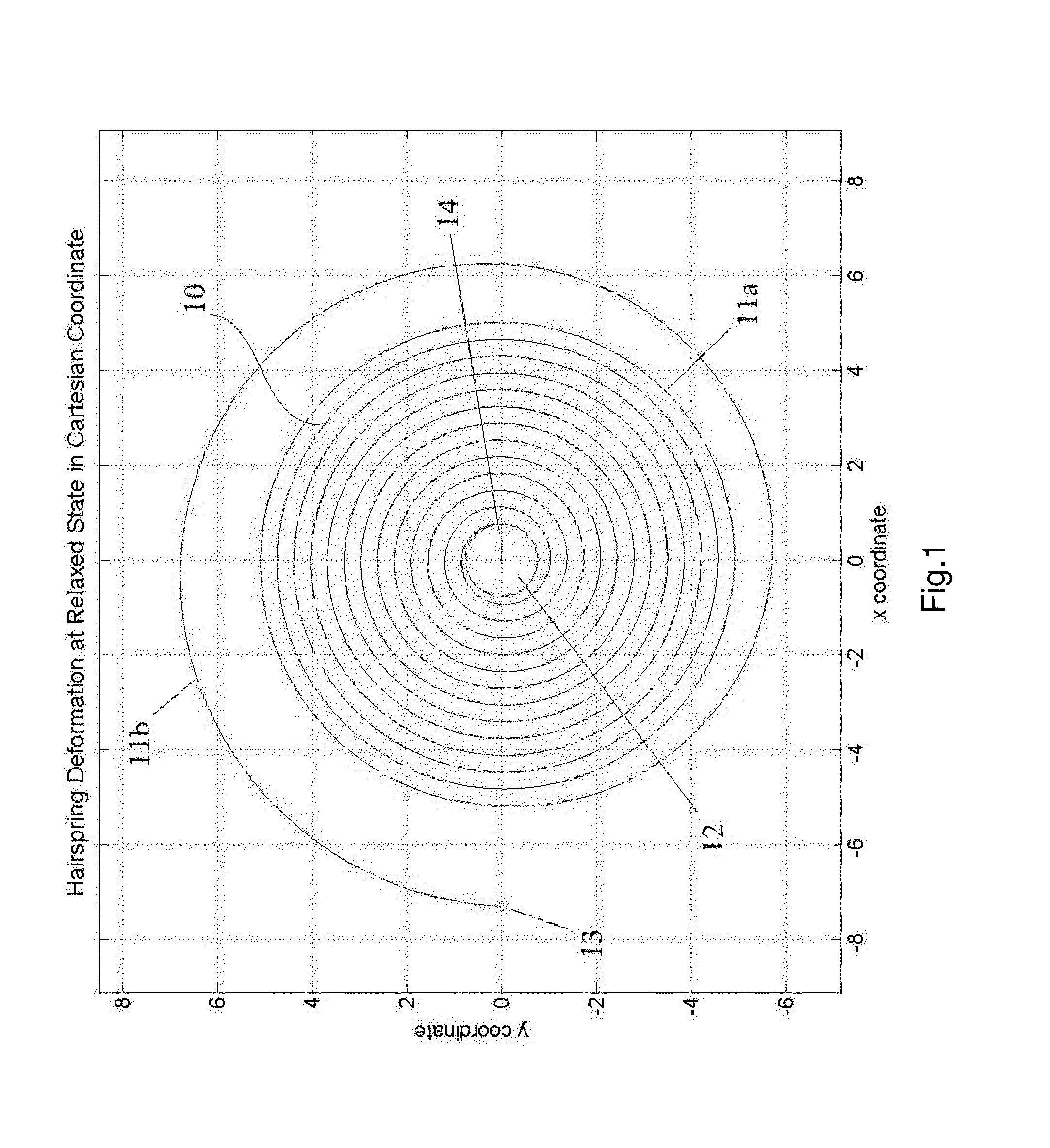
[0139]Referring to FIG. 1, for illustrative and explanatory purposes a simplified schematic diagram of traditional hairspring 10 at its relaxed state having a total of 13.5 turnings is shown.

[0140]The hairspring turnings consist of two sections namely the main body section 11a and outer section 11b. The main body section 11a forms an Archimedes spiral having constant pitch with its inner terminal connected to a collet 12. The collet 12 is in turn rigidly connected to a balance wheel (not shown). The outer section 11b has a significantly increased pitch to allow room for the stud 13 placement. All portions of 11a and 11b have a constant cross section.

[0141]The line 14 presents the connection point between the collet 12 and hairspring main body section 11a which allows the reader to better track the collet 12 rotation angle.

[0142]As will be appreciated by those skilled in the art, the traditional hairspring 10 is only an example of the many possible hairspring shape, but this example ...


PUM

PropertyMeasurementUnit
Lengthaaaaaaaaaa
Forceaaaaaaaaaa
Widthaaaaaaaaaa

Abstract

A method of increasing concentricity in use of a spiral hairspring mechanical timepiece; the hairspring having an inner terminal end portion for engagement with a collet, an outer terminal end portion for engagement with a stud, a first limb portion extending from the inner terminal end portion towards the outer terminal end portion, and a stiffening portion positioned at the outer turn of the hairspring and having a cross-sectional second moment of area different to that of the first limb portion such that bending stiffness of the stiffening portion has a greater bending stiffness than the single limb portion. The method includes modifying cross-sectional second moments of an area of the first limb portion and the stiffening portion by minimizing a cost function throughout the amplitude of the rotation of hairspring in use, the cost function being correlated to the net concentricity of the hairspring.

Description

FIELD OF THE INVENTION[0001]The invention concerns a new design for a hairspring of a mechanical timepiece. More particularly, the present invention relates to a hairspring and a method of design thereof for increased concentricity during the operation of a mechanical timepiece.BACKGROUND OF THE INVENTION[0002]A hairspring is a key component in a mechanical timepiece. A hairspring is one of the two main components of an oscillator of a timepiece, the other being the balance wheel. The oscillator provides the means of time regulation via its simple harmonic motion.[0003]A balance wheel acts as the inertial element, and is engaged with the inner terminal of a spiral-shaped hairspring. The spiral geometry of a hairspring is generally provided in the form of an Archimedean spiral, generally having a constant pitch. The outer terminal of the hairspring is generally fixedly attached to a fixed stud.[0004]Ideally, the hairspring provides a restoring torque to the balance wheel that is prop...

Claims


Application Information

Patent Timeline
IPC IPC(8): G04B17/06
CPCG04B17/066G04B17/06Y10T29/49581
Inventor CHING, HO
Owner MASTER DYNAMIC LTD
Why Eureka
Try Eureka