Variable machine tool capable of multi-axis machining

a multi-axis machine tool and variable technology, applied in the direction of manufacturing tools, other manufacturing equipment/tools, metal-working machine components, etc., can solve the problems of affecting the quality of the product, the difficulty of fine and complicated shape processing, and the inability to meet the needs of the customer, so as to simplify the configuration of the multi-axis machine tool, improve the processing efficiency, and perform more complex and finer processing.

Active Publication Date: 2014-01-23
KOREA INST OF MASCH & MATERIALS
View PDF4 Cites 12 Cited by
  • Summary
  • Abstract
  • Description
  • Claims
  • Application Information

AI Technical Summary

Benefits of technology

[0023]According to the variable machine tool capable of multi-axis machining according to the exemplary embodiment of the present invention, processability may be improved compared to the related art by applying a driving mechanism in which a rotary motion is maximized. Particularly, the variable machine tool capable of multi-axis machining according to the exemplary embodiment of the present invention may be used even in the BT and IT micro processing fields.
[0024]Particularly, by simultaneously applying a mechanical structure capable of performing a two-axial rotary motion and three-axial translation, it is possible to simplify a complex configuration of the multi-axis machine tool of the related art compared to the related art and perform more complex and finer processing.
[0025]Further, according to the variable machine tool capable of multi-axis machining according to the exemplary embodiment of the present inve...

Problems solved by technology

However, since most of the multi-axis machine tools have a large body volume, and a tool performs processing while moving vertically, forward and backward, and horizontally around a processing target of which a position is fixed on a table in order to three-dimensionally process the processing target, a processing error is increased according to an increase in a movement distance of the tool, thereby causing slight difficulty in processing a product with a fine and complicated sh...

Method used


Image

  • Variable machine tool capable of multi-axis machining
  • Variable machine tool capable of multi-axis machining
  • Variable machine tool capable of multi-axis machining

Examples


Embodiment Construction

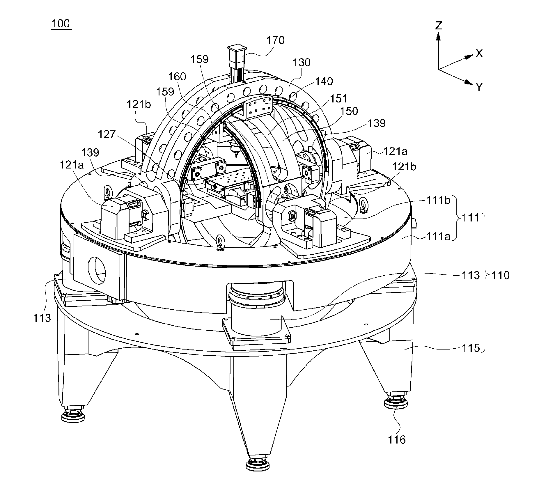
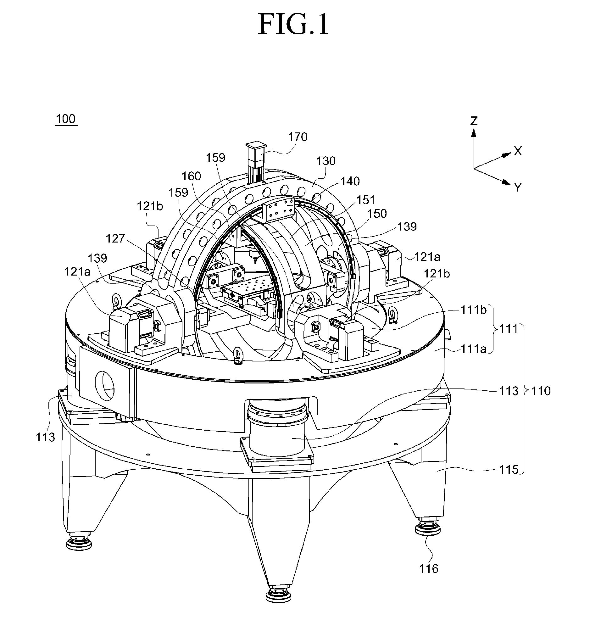
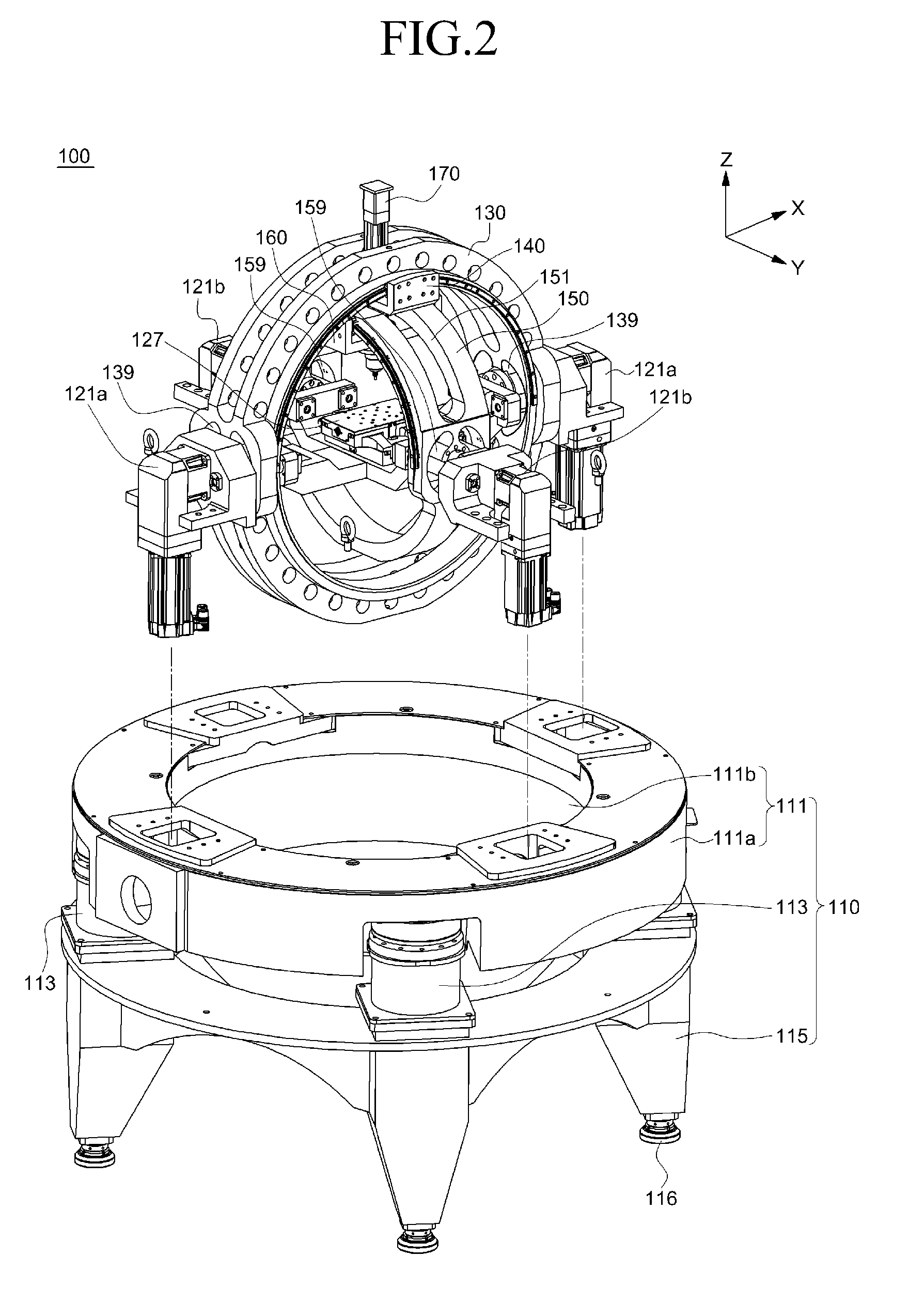
[0034]Hereinafter, a variable machine tool capable of multi-axis machining (hereinafter, simply referred to as a “variable machine tool”) according to an exemplary embodiment of the present invention will be described with reference to the accompanying drawings.

[0035]An advantage and a characteristic of the present invention, and a method for achieving the advantage and the characteristic may become clear with reference to the exemplary embodiments described in detail below with reference to the accompanying drawings. However, the present invention is not limited by exemplary embodiments disclosed below, but may be variously implemented into different forms. These embodiments are provided for full disclosure of the present invention and for full understanding of the scope of the present invention by those skilled in the art. In the following description, detailed explanation of known related functions and constitutions may be omitted to avoid unnecessarily obscuring the subject matt...


PUM

PropertyMeasurementUnit
Diameteraaaaaaaaaa
Sizeaaaaaaaaaa

Abstract

According to an exemplary embodiment of the present invention, a variable machine tool capable of multi-axis machining includes: a base frame; a first rotating frame rotating on the base frame and comprising a first sliding member sliding along a circumference while being contact-supported through an interior diameter; a second rotating frame cross-disposed inside the first rotating frame to rotate in a direction crossing the first rotating frame, and comprising a second sliding member sliding along a circumference while being contact-supported through an interior diameter; and a spindle of which position and posture displacement is adjusted when the first sliding member and the second sliding member slide by interworking with rotation of the first rotating frame and the second rotating frame, the spindle being installed while passing through the first sliding member and the second sliding member.

Description

CROSS-REFERENCE TO RELATED APPLICATION[0001]This application claims priority to and the benefit of Korean Patent Application No. 10-2012-0078735 filed in the Korean Intellectual Property Office on Jul. 19, 2012, the entire contents of which are incorporated herein by reference.BACKGROUND OF THE INVENTION[0002](a) Field of the Invention[0003]The present invention relates to a variable machine tool capable of multi-axis machining, and more particularly, to a variable machine tool capable of multi-axis machining capable of performing 5 axes processing, to which an apparatus mechanism in which a rotary motion is maximized through a two-axial rotary motion and three-axial translation is applied, thereby improving processability compared to a variable machine tool capable of multi-axis machining in the related art, and thus being utilized in various fields (for example, BT and IT micro processing fields).[0004](b) Description of the Related Art[0005]A representative introduced apparatus u...

Claims


Application Information

Patent Timeline
IPC IPC(8): B23C1/12
CPCB23C1/12B23Q1/44B23Q1/5425B23Q2210/006Y10T409/304088Y10T409/304312Y10T409/308512Y10T409/309576B23P23/04B23Q1/25B23K26/346B23Q1/015B23Q1/03B23Q1/5406B23Q11/0032
Inventor PARK, JONG-KWEONLEE, SUNG CHEULRO, SEUNG KOOKKIM, BYUNG-SUB
Owner KOREA INST OF MASCH & MATERIALS
Why Eureka
Try Eureka