Power supply apparatus and vehicle having the same

a technology of power supply apparatus and power supply vehicle, which is applied in the direction of cell components, cell components, propulsion by batteries/cells, etc., can solve the problems of unintentional turning on electricity, and achieve the effect of preventing unintentional electric conduction or corrosion and preventing the harmful influence of the battery cell stack

Inactive Publication Date: 2014-01-23
SANYO ELECTRIC CO LTD
View PDF1 Cites 85 Cited by
  • Summary
  • Abstract
  • Description
  • Claims
  • Application Information

AI Technical Summary

Benefits of technology

[0008]In order to achieve the above object, according to a power supply apparatus of a first aspect of the present invention, the power supply apparatus includes: a battery cell stack obtained by stacking a plurality of battery cells; and a cover case surrounding an outside of the battery cell stack, wherein a resin can be poured between the battery cell stack and the cover case,

Problems solved by technology

Such condensation may unintentionally

Method used


Image

  • Power supply apparatus and vehicle having the same
  • Power supply apparatus and vehicle having the same
  • Power supply apparatus and vehicle having the same

Examples


embodiment 1

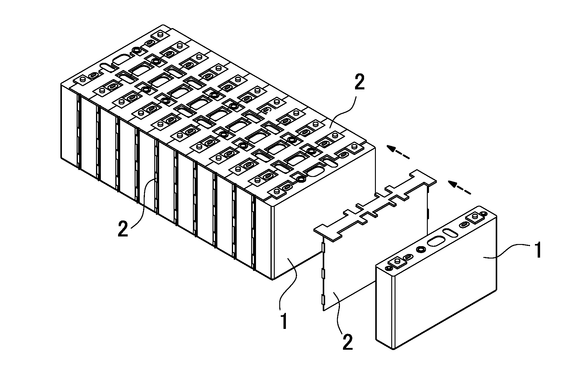
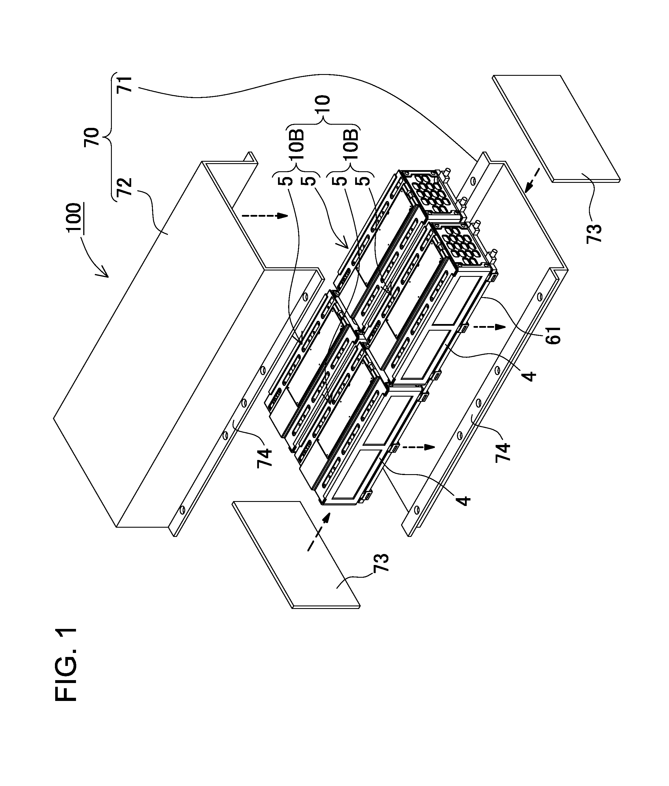
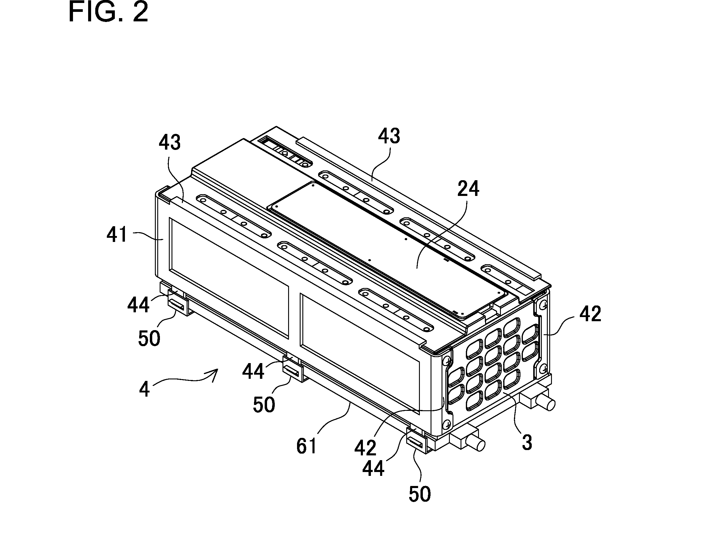
[0048]An example of a power supply apparatus 100 according to Embodiment 1 of the present invention applied to an on-board power supply apparatus will be described in FIGS. 1 to 10. In these figures, FIG. 1 is an exploded perspective view of the power supply apparatus 100, FIG. 2 is a perspective view of a battery cell stack 5 in FIG. 1, FIG. 3 is an exploded perspective view illustrating the battery cell stack 5 in FIG. 2 having a cooling plate 61 removed therefrom, FIG. 4 is a perspective view of the battery cell stack 5 in FIG. 2 diagonally viewed from a lower part, FIG. 5 is an exploded perspective view of the battery cell stack 5 in FIG. 2, FIG. 6 is an exploded perspective view of the battery cell stack 5 in FIG. 5, FIG. 7 is a perspective view of an inner case 21, FIG. 8 is an exploded perspective view illustrating a state where the battery cell stack 5 in FIG. 6 is inserted into the inner case 21 in FIG. 7, FIG. 9 is a schematic sectional view illustrating an example of prov...

embodiment 2

[0090]According to the configuration in Embodiment 1, the inner case provided between the battery cell stack and the fastening member needs to be newly designed. Therefore, an existing power supply apparatus cannot be used as it is. In order to use an existing battery cell stack and fastening member as well as achieve the waterproof structure, the inner case can be formed into a size large enough for housing the battery cell stack that has been fastened by the fastening member. Such a configuration will be described as Embodiment 2 with reference to FIGS. 13 to 18. In these figures, FIG. 13 is a perspective view of a battery cell stack 5B in a power supply apparatus according to Embodiment 2, FIG. 14 is an exploded perspective view illustrating the battery cell stack 5B in FIG. 13 having the cooling plate 61 removed therefrom, FIG. 15 is an exploded perspective view of the battery cell stack 5B in FIG. 14, FIG. 16 is an exploded perspective view of the battery cell stack 5B in FIG. ...

embodiment 3

[0094]According to the above configuration, an existing battery cell stack can be housed in the inner case, followed by potting or the like, thereby easily achieving the waterproof structure.

[0095]Meanwhile, a part where there is a high probability of forming condensation is a contact surface with the cooling plate. Then, if not the whole battery cell stack but only the contact surface with the cooling plate or the vicinity thereof is covered with the cushioning member, downsizing is achieved. Such an example is shown as Embodiment 3 in FIGS. 19 to 20. In these figures, FIG. 19 is a perspective view of a battery cell stack 5C according to Embodiment 3, and FIG. 20 is an exploded perspective view of FIG. 19. In this battery cell stack 5, a circumference thereof is not completely blocked for the waterproof structure. Only a bottom surface of the contact surface with the cooling plate 61 is covered with the cushioning member 18.

(Heat Shrinkable Tube)

[0096]As shown in FIG. 21A, 21B, a s...


PUM


Abstract

A power supply apparatus includes: a battery cell stack obtained by stacking a plurality of battery cells; and a cover case surrounding an outside of the battery cell stack, in which a resin is poured between the battery cell stack and the cover case, achieving a waterproof structure of making the battery cell stack waterproof. This allows prevention of water entering from an outside, thereby preventing unintentional electric conduction or corrosion. A gap between the battery cell stack and the cover case is also eliminated to prevent the harmful influence on the battery cell stack due to condensation inside the cover case.

Description

BACKGROUND OF THE INVENTION[0001]1. Field of the Invention[0002]The present invention mainly relates to a power supply apparatus for a large current that is used for a power supply of a motor driving an automobile such as a hybrid automobile or an electric automobile, for household use, for electrical storage in industrial use or the like, and a vehicle having the same.[0003]2. Description of the Related Art[0004]A power supply apparatus having an output increased such as a battery pack for vehicles has been demanded. In such a power supply apparatus, an output voltage and an output power are increased by connecting a large number of battery cells in series. The battery cell is charged or discharged with a large current, leading to heat generation. In particular, an amount of the heat generation increases in accordance with an increase of the number of battery cells to be used. Therefore, demanded is a heat radiation mechanism in which heat radiated from the battery cell is efficien...

Claims


Application Information

Patent Timeline
IPC IPC(8): H01M2/10H01M50/209H01M50/271
CPCH01M2/1094H01M2/1083H01M10/625H01M10/647H01M10/6556H01M10/6555H01M10/613B60L50/64Y02T10/70Y02E60/10H01M50/24H01M50/209H01M50/271
Inventor HASHIMOTO, HIROYUKITSUCHIYA, MASAKIASAI, YASUHIROSETO, TAKASHIKOMORIYA, TAKAHIDE
Owner SANYO ELECTRIC CO LTD
Why Eureka
Try Eureka