
Fuel supply device for internal combustion engine

a technology for internal combustion engines and fuel supply devices, which is applied in the direction of liquid fuel feeders, machines/engines, mechanical equipment, etc., can solve the problems of inconvenient fuel system closure, disadvantageous small differential pressure, and relatively small delivery pressure of fuel by ordinary diaphragm pumps. achieve the effect of preventing oil mist from entering and increasing the fuel delivery pressur

Inactive Publication Date: 2014-01-30
HONDA MOTOR CO LTD
View PDF6 Cites 8 Cited by
  • Summary
  • Abstract
  • Description
  • Claims
  • Application Information

AI Technical Summary

Benefits of technology

The aim of this invention is to improve the technique of crankcase oil mist prevention and increase fuel delivery pressure using the diaphragm pump.

Problems solved by technology

However, delivery pressure with which fuel is discharged or delivered by an ordinary diaphragm pump is relatively small.
Such small differential pressure is disadvantageous if it is desired to increase accuracy of a flow rate of fuel to be supplied from the injector to a combustion chamber.
Note that the “vapor lock” is a phenomenon where air bubbles are produced by liquid fuel being vaporized by ambient heat and thus a fuel system is undesirably closed with the thus-produced air bubbles.
In case the oil mist enters the diaphragm pump, it can undesirably adhere to components parts within the diaphragm pump.

Method used


Image

  • Fuel supply device for internal combustion engine
  • Fuel supply device for internal combustion engine
  • Fuel supply device for internal combustion engine

Examples


Embodiment Construction

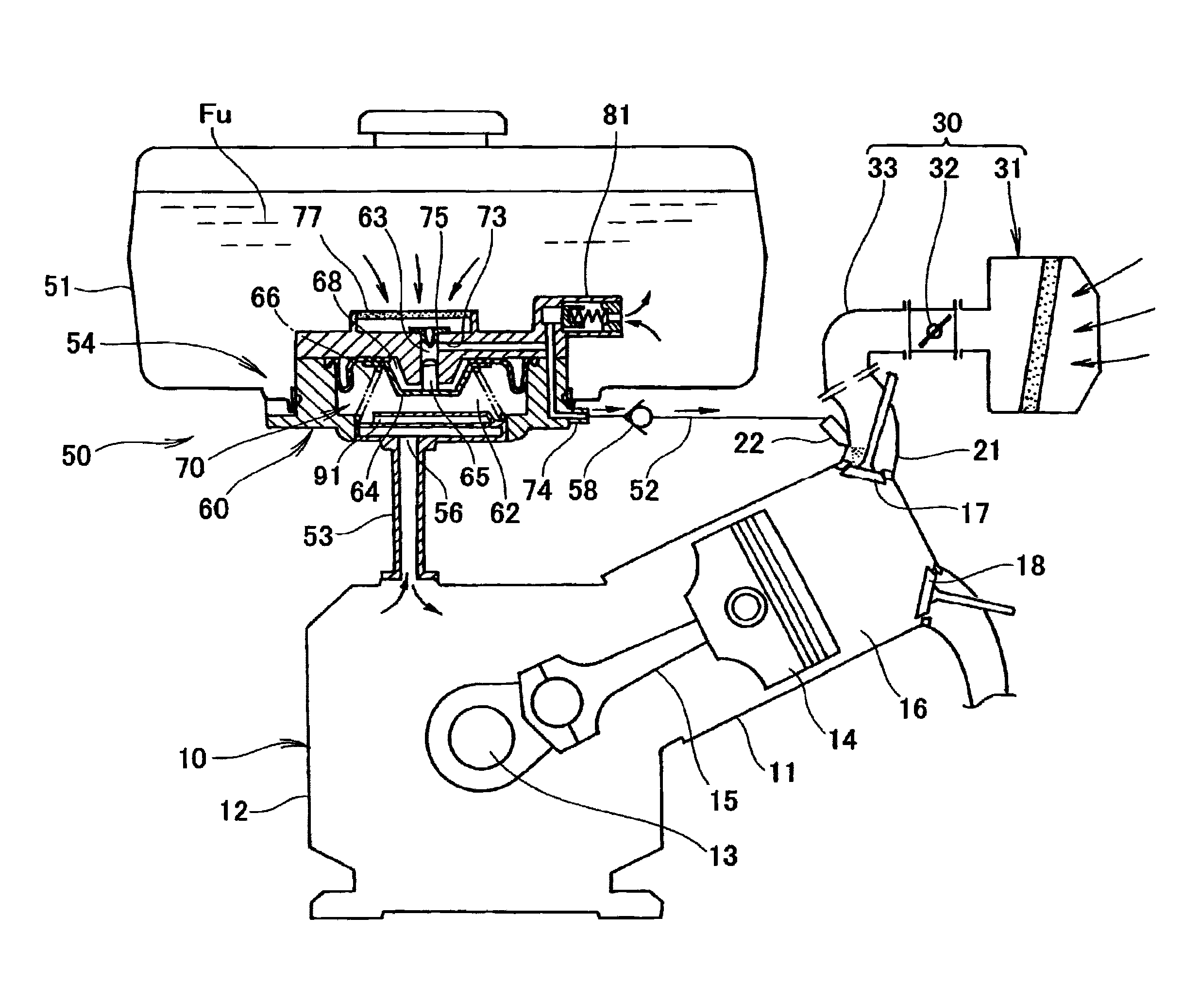
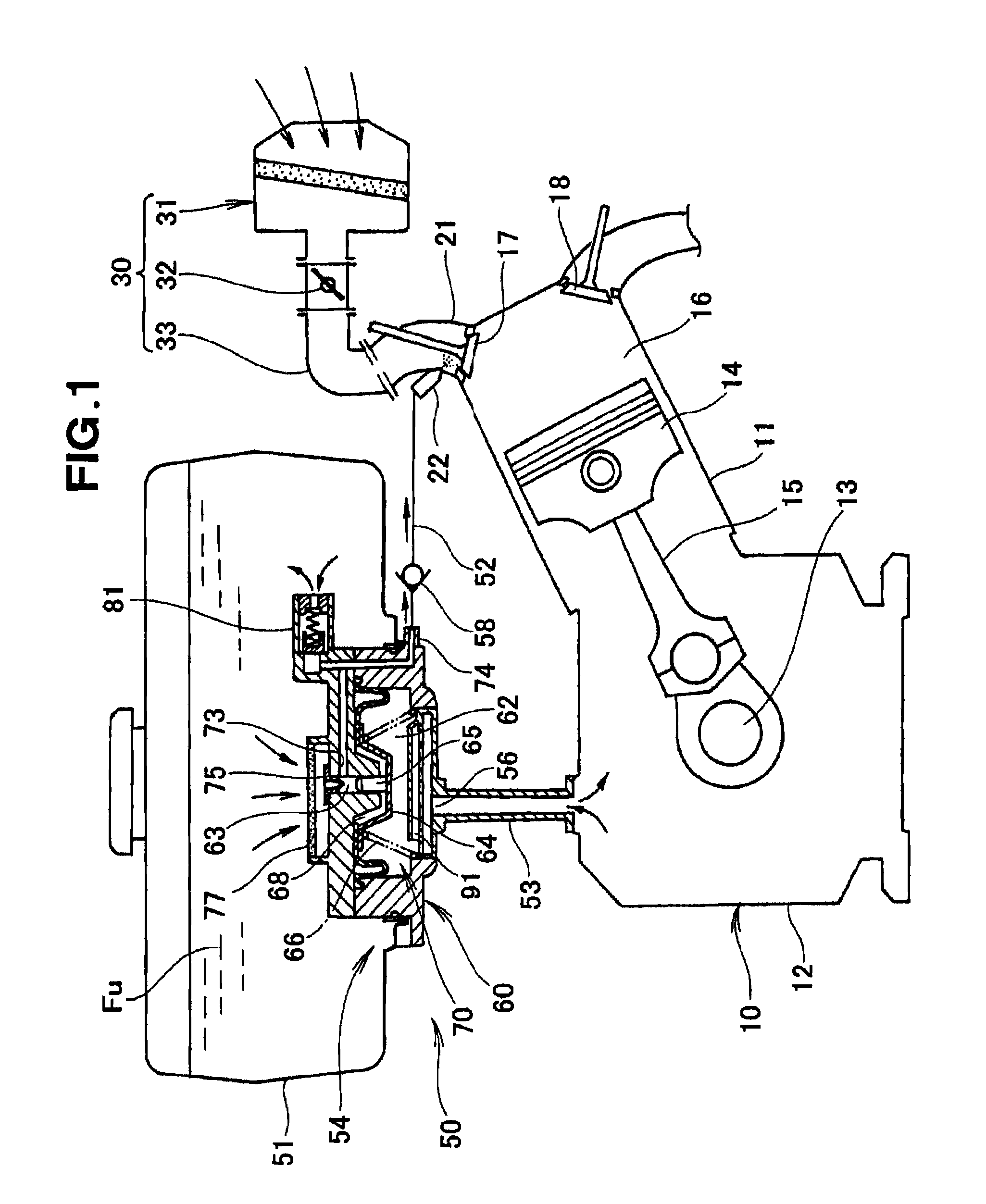
[0025]FIG. 1 schematically shows an internal combustion engine 10 provided with an embodiment of a fuel supply device 50 of the present invention. As shown in FIG. 1, the internal combustion engine 10, which is, for example, a transverse-mounted, single-cylinder four-cycle engine, includes as its main elements: a crankcase 12 integrally having a cylinder 11 oriented upward; a crankshaft 13 disposed horizontally; a piston 14; a con rod 15; a combustion chamber 16; an intake valve 17; and an exhaust valve 18.

[0026]An intake system 30 for the internal combustion engine 10 includes an air cleaner 31, a throttle valve 32 and an intake pipe 33. The intake pipe 33 is connected to an intake port 21 of the internal combustion engine 10. An injector 22 for supplying fuel Fu into the intake port 21 is provided in the intake port 21.

[0027]In order to lubricate sliding portions accommodated in the crankcase 12, the internal combustion engine 10 is constructed to produce oil mist within the crank...


PUM


Abstract

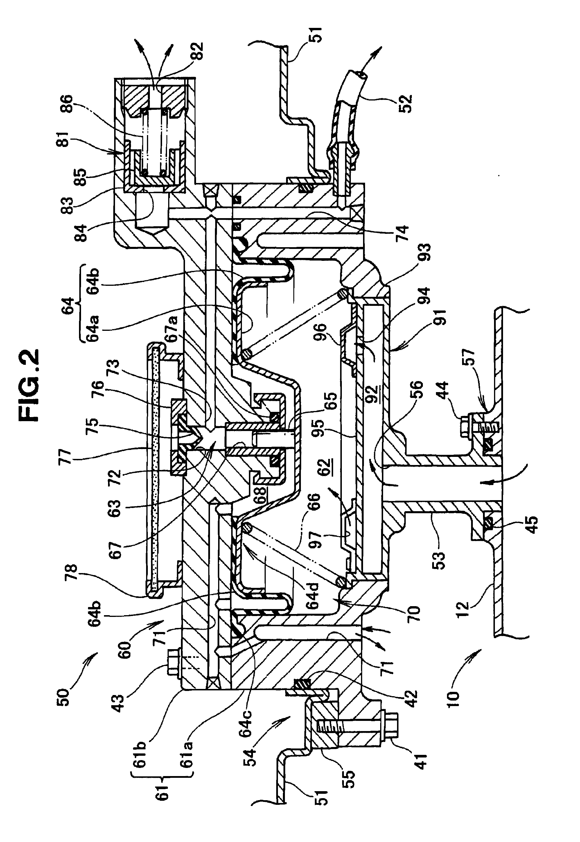
A fuel supply device supplies fuel from a fuel tank to an injector by driving a diaphragm pump by use of pressure variation within a crankcase. The diaphragm pump includes: a pump casing; a diaphragm partitioning the interior of the pump casing into a negative pressure chamber and a pump chamber; and a plunger connected to the diaphragm and reciprocatively movable to and from the pump chamber. A pressure receiving area over which the plunger receives, at its end surface in a plunger advancing / retracting direction, pressure from the pump chamber is set smaller than a pressure receiving area over which the diaphragm receives pressure from the negative pressure chamber in the advancing / retracting direction.

Description

FIELD OF THE INVENTION[0001]The present invention relates generally to fuel supply devices for internal combustion engines which include an injector for supplying fuel to an intake port, and more particularly to a technique for supplying fuel from a fuel tank to an injector by use of pressure variation within a crankcase.BACKGROUND OF THE INVENTION[0002]Among the conventionally-known schemes for supplying fuel from a fuel tank to an internal combustion engine are a first fuel supply scheme in which fuel is supplied from the fuel tank to a carburetor, and a second fuel supply scheme in which fuel is supplied from the fuel tank to an injector. The second fuel supply scheme has been popularly used in recent years because it allows a fuel injection amount of the injector to be controlled finely by means of an electronically-controlled fuel injection device. An example of such a fuel supply device for an internal combustion device is disclosed in Japanese Patent Application Laid-Open Pub...

Claims


Application Information

Patent Timeline
Patent Type & Authority Applications(United States)
IPC IPC(8): F02M69/02
CPCF02M69/02F02M37/046F02M69/044F02M37/007
Inventor TSUTSUI, TOSHIHIROMORINAGA, RYOTA
Owner HONDA MOTOR CO LTD
Learn More