System and method for a rechargeable battery

a rechargeable battery and system technology, applied in the direction of electric vehicles, circuit monitoring/indication, transportation and packaging, etc., can solve the problems of premature deterioration of damage to the electrochemical cells of the battery, and unsatisfactory battery performance, etc., to reduce the charge voltage, and reduce the charge voltag

Active Publication Date: 2014-01-30
GENERAL ELECTRIC CO
View PDF2 Cites 11 Cited by
  • Summary
  • Abstract
  • Description
  • Claims
  • Application Information

AI Technical Summary

Benefits of technology

[0007]In another embodiment, the method includes establishing a state of charge of the rechargeable battery when the top of charge condition is identified. In another embodiment, the state of charge corresponds to a known available energy capacity of the rechargeable battery. In another embodiment, the charge voltage is a float voltage of the rechargeable battery, and wherein the state of charge is established as 100%. In another embodiment, the charge voltage is not a float voltage of the rechargeable battery, and the state of charge is established based on the charge voltage and the float voltage. In another embodiment, the method includes ceasing to charge the rechargeable battery when the top of charge condition is identified. In another embodiment, the defined time period is no more than 120 seconds. In another embodiment, the voltage tolerance is no more than 10 millivolts per cell of the rechargeable battery. In another embodiment, the current tolerance is no more than 500 milliamps. In another embodiment, the threshold current is zero amps. In another embodiment, the rechargeable battery comprises a plurality of sodium-metal-halide cells.
[0008]In another embodiment, a method for a rechargeable battery includes applying a charge voltage to the rechargeable battery; monitoring a battery voltage and a battery current of the rechargeable battery; calculating a battery resistance from the battery voltage and the battery current; and identifying a top of charge condition when for a defined time period the battery voltage is within a tolerance of the charge voltage and the calculated battery resistance is greater than a threshold resistance.
[0009]In another embodiment, calculating the battery resistance comprises calculating a per cell resistance for a plurality of energy storage cells of the rechargeable battery. In another embodiment, the threshold resistance is 80 milliohms.
[0010]In yet another embodiment, a method for a rechargeable battery includes monitoring a battery voltage and battery current of the rechargeable battery; applying a charge voltage to the rechargeable battery at a voltage level that is greater than a float voltage of the rechargeable battery; reducing the charge voltage to the float voltage; and identifying a top of charge condition when for a defined time period the battery voltage is within a voltage tolerance of the float voltage and the battery current is within a tolerance of zero amps.
[0011]In another embodiment, the method includes establishing a state of charge of the rechargeable battery when the top of charge condition is identified. In another embodiment, the state of charge is established as 100% when the top of charge condition is identified. In another embodiment, the voltage tolerance is no more than 10 millivolts. In another embodiment, the voltage level is at least 1% greater than the float voltage.
[0012]In another embodiment, reducing the charge voltage to the float voltage further includes reducing the charge voltage to the float voltage upon achieving a designated state of charge, reducing the charge voltage to the float voltage after a designated charging time, reducing the charge voltage to the float voltage when the battery current falls below a designated threshold current, or reducing the charge voltage to the float voltage when the battery voltage exceeds a designated threshold voltage.

Problems solved by technology

In some situations, how a rechargeable battery is charged and discharged may result in undesired battery performance and premature deterioration of the electrochemical cells of the battery.
For example, repeated over or under charging of a rechargeable battery may damage its electrochemical cells.
Over charging batteries has also lead to battery failures.
Such systems have been susceptible to changes in the charge voltage that have led to over and under charging and reduced performance.
However such systems have required precise current measurement that substantially increases the cost of a rechargeable battery system.
Moreover, the magnitude of errors in the monitored charge of the battery tends to increase over time through successive charge and discharge cycles resulting in reduced battery performance.
However for some batteries, the open circuit voltage does not correlate well to the total energy stored.
These prior systems have not provided a consistent indication of the useful power contained in the battery, which has adversely affected the efficiency of the charge and discharge operations.

Method used


Image

  • System and method for a rechargeable battery
  • System and method for a rechargeable battery
  • System and method for a rechargeable battery

Examples


Embodiment Construction

[0022]The subject matter disclosed herein relates to a rechargeable battery system and method for a rechargeable battery system. Referring generally to FIGS. 1 through 6, embodiments of a rechargeable battery system and method of operating a rechargeable battery system are disclosed.

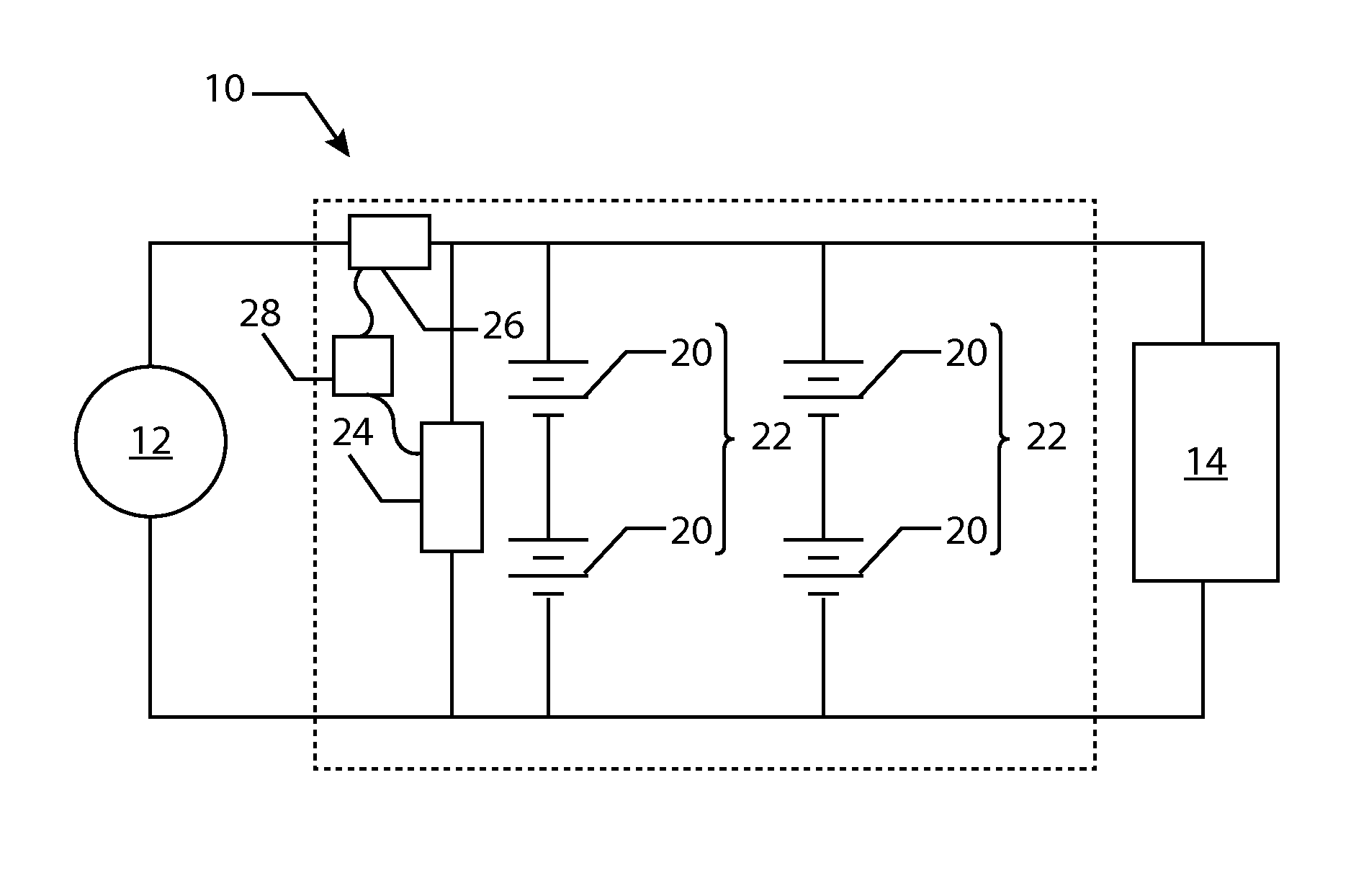
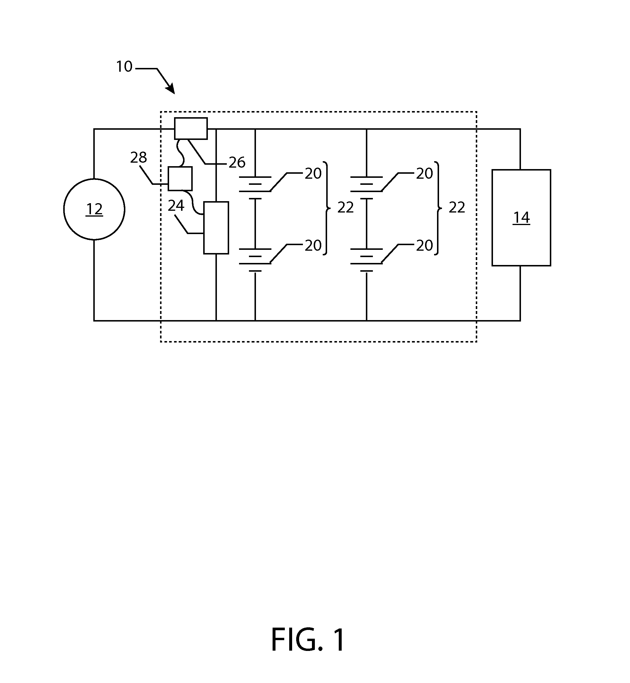
[0023]Referring to FIG. 1, an embodiment of a rechargeable battery system is illustrated, which has a rechargeable battery 10 connected between a source 12 and a load 14. The source 12 may be a variety of electrical power generation devices or systems. In one embodiment, the source 12 is a regenerative brake system of a vehicle, such as an automobile or train. In another embodiment, the source 12 is an internal combustion engine in combination with a generator or alternator configured to produce electrical power. In yet another embodiment, the source 12 is an electricity distribution system, such as a national power grid, electric utility or other commercially available electrical supply. In various embo...


PUM


Abstract

A method for a rechargeable battery is disclosed that includes applying a charge voltage to the rechargeable battery; monitoring a battery voltage and a battery current of the rechargeable battery; and identifying a top of charge condition when for a defined time period the battery voltage is within a voltage tolerance of the charge voltage and the battery current is within a current tolerance of a threshold current. Also disclosed is a rechargeable battery system.

Description

BACKGROUND[0001]1. Technical Field[0002]Embodiments of the subject matter disclosed herein relate to rechargeable batteries and methods of recharging rechargeable batteries.[0003]2. Dicussion of Art[0004]In some situations, how a rechargeable battery is charged and discharged may result in undesired battery performance and premature deterioration of the electrochemical cells of the battery. For example, repeated over or under charging of a rechargeable battery may damage its electrochemical cells. Over charging batteries has also lead to battery failures. In prior systems, a battery has been recharged by applying a voltage to the battery and charging until the battery ceases to draw current from the charging source. Such systems have been susceptible to changes in the charge voltage that have led to over and under charging and reduced performance. In other systems, the total charge in the battery is monitored by integrating current to and from the battery. However such systems have ...

Claims


Application Information

Patent Timeline
Patent Type & Authority Applications(United States)
IPC IPC(8): H02J7/00
CPCH02J7/0048H02J7/0049H02J7/00
Inventor BOURGEOIS, RICHARD SCOTTBOCCANFUSO, VINCENT
Owner GENERAL ELECTRIC CO
Why Eureka
Try Eureka