Entertainment, lighting and climate control system

a technology for lighting and climate control systems, applied in transmission systems, automatic controllers, transmission systems, etc., can solve the problems of inefficiency in placement, integration and operation of communications and media devices and related infrastructure, obtrusive and unsightly, and under-served users

Active Publication Date: 2014-01-30
KARAM BRIAN W
View PDF51 Cites 4 Cited by
  • Summary
  • Abstract
  • Description
  • Claims
  • Application Information

AI Technical Summary

Benefits of technology

[0020]In an embodiment of the method, a step of providing a controller configured to implement control signals based on input from a user, and for controlling the function of the communications devices, may be included.

Problems solved by technology

This results in inefficiencies in terms of placement, integration and operation of communications and media devices and related infrastructure (which includes, for example, wiring, modems, receiver boxes, control panels).
These inefficiencies manifest themselves through obtrusive and unsightly placement of wiring, redundancy or lack of conveniently located outlets for attachment of wired devices and related hardware.
This can result in under served users or inefficient use of resources such as electricity, through running more devices than needed to accomplish certain goals.
As systems have been installed in a piece meal manner, difficulties arise in securing service or maintenance thereof.
Multiple providers may need to be engaged, heightening costs and increasing the time needed for maintenance or repairs.
This can result in costly downtime in business applications and / or inconvenience in residential applications.
This is particularly problematic in smaller commercial or residential properties (e.g., condominiums) where space is precious and post-construction alterations are quite onerous if not entirely impractical.
Related disparities in systems lead to duplications of hardware and exacerbate the problems discussed above.

Method used


Image

  • Entertainment, lighting and climate control system
  • Entertainment, lighting and climate control system
  • Entertainment, lighting and climate control system

Examples


Embodiment Construction

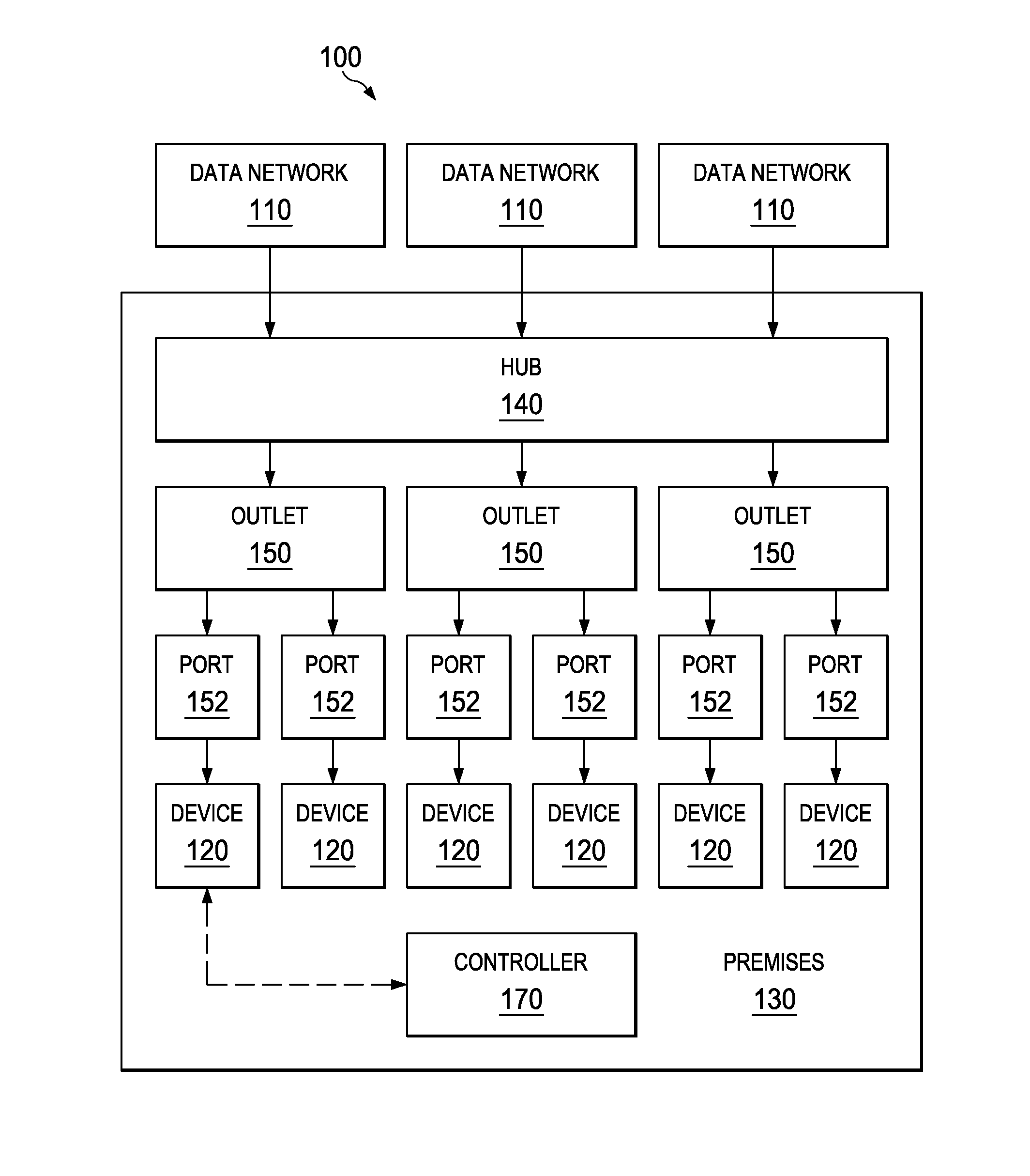
[0030]The current disclosure enables a system 100 for connecting one or more data networks 110 to one or more communications devices 120 in a premises 130. The system 100, shown in FIG. 1 in a schematic manner, comprises a hub 140 that is located within the premises 130 and is connected to the data networks 110. Data networks 110 may include, for example, fibre-optic and other digital data connections provided by Internet service providers (such as carriers), but may also include connections to external servers of providers of security, climate control and other systems. Devices 120 provided as part of or for use with the system may include, for example, home theatre equipment, multi-room music systems, lighting systems, security integration systems and related equipment, and comfort and energy management systems, including climate control systems.

[0031]The hub 140 may comprise a 34″×14″ or similarly sized structured wiring panel cabinet 140, for example, as shown in FIGS. 7 and 8. ...


PUM


Abstract

Disclosed herein is a system for connecting one or more data networks to a plurality of communications devices in a premises, and methods of installing same. The system includes a hub located within the premises and connected to the data networks, as well as one or more conduits connected to the hub for connecting the data networks to one or more outlets in the premises. The outlets are adapted to connect to the communications devices to allow the user access to the networks.

Description

CROSS REFERENCE TO RELATED APPLICATION[0001]This application claims priority to U.S. Provisional Patent Application No. 61 / 674,685, entitled “Smart Home Network,” filed Jul. 23, 2012, which is hereby incorporated by reference in its entirety for all purposes.TECHNICAL FIELD[0002]This disclosure relates generally to systems for automation of residential and commercial premises and, more particularly, to an entertainment, lighting and climate control system.BACKGROUND[0003]Owners and occupiers of modern residential and commercial premises have come to expect to have available infrastructure to allow use of a variety of communications and media devices. This includes access to, for example, entertainment, office equipment, lighting, security, climate control and automation technologies. This typically requires connection of the premises to multiple outside service providers and entails the use of many devices to access such services.[0004]In most premises, on-site infrastructure has be...

Claims


Application Information

Patent Timeline
Patent Type & Authority Applications(United States)
IPC IPC(8): G05B15/02
CPCG05B15/02H04L12/2834H04L12/2898
Inventor KARAM, BRIAN W.
Owner KARAM BRIAN W
Why Eureka
Try Eureka