Backlight module and assembly method thereof

Active Publication Date: 2014-01-30
AU OPTRONICS CORP
View PDF9 Cites 0 Cited by
  • Summary
  • Abstract
  • Description
  • Claims
  • Application Information

AI Technical Summary

Benefits of technology

The present invention provides a backlight module that can solve problems of light leakage and uneven backlight caused by detachment between the light emitting surface of the light emitting module and the light incident surface of the light guide plate. The light emitting module can rotate when being assembled, allowing the light emitting surface to contact with the light incident surface of the light guide plate by a plane contact manner. This increases brightness and efficiency of the backlight module. The assembly method of the backlight module can easily adjust angles of the light emitting module and then fix the light emitting module on the reflection cover, further improving assembly efficiency.

Problems solved by technology

If the light emitting surface of the light source and the light incident surface of the light guide plate are not contacted with each other by a plane contact manner due to dimension tolerance or poor assembly, the light generated by the light source can not fully enter the light guide plate, and thus cause problems of light leakage and uneven backlight, such that the side-light type backlight module may have poor efficiency.

Method used


Image

  • Backlight module and assembly method thereof
  • Backlight module and assembly method thereof
  • Backlight module and assembly method thereof

Examples


Embodiment Construction

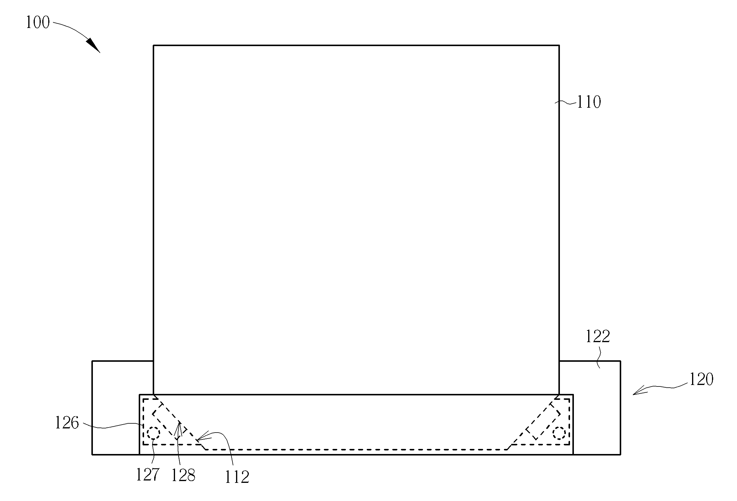
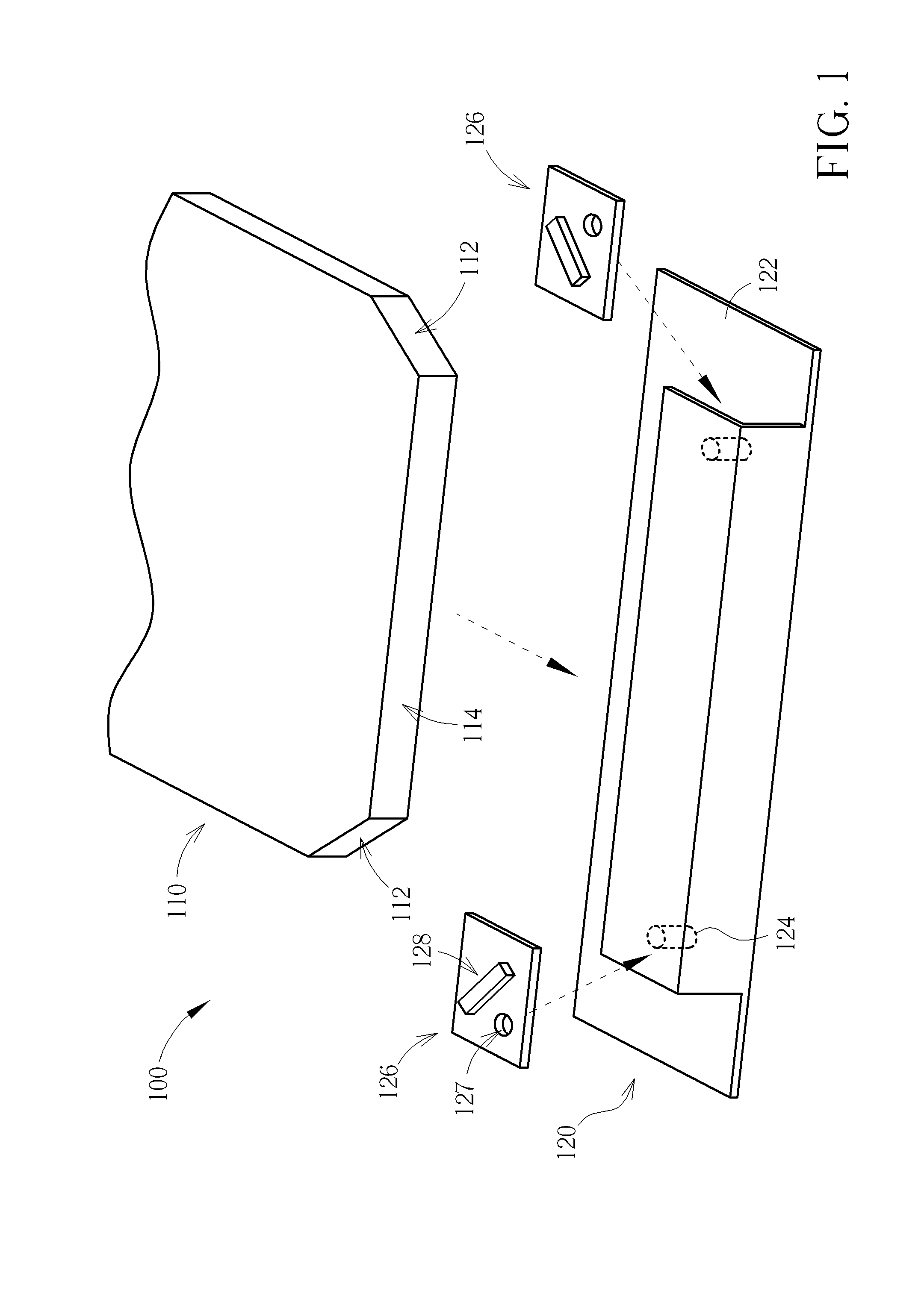
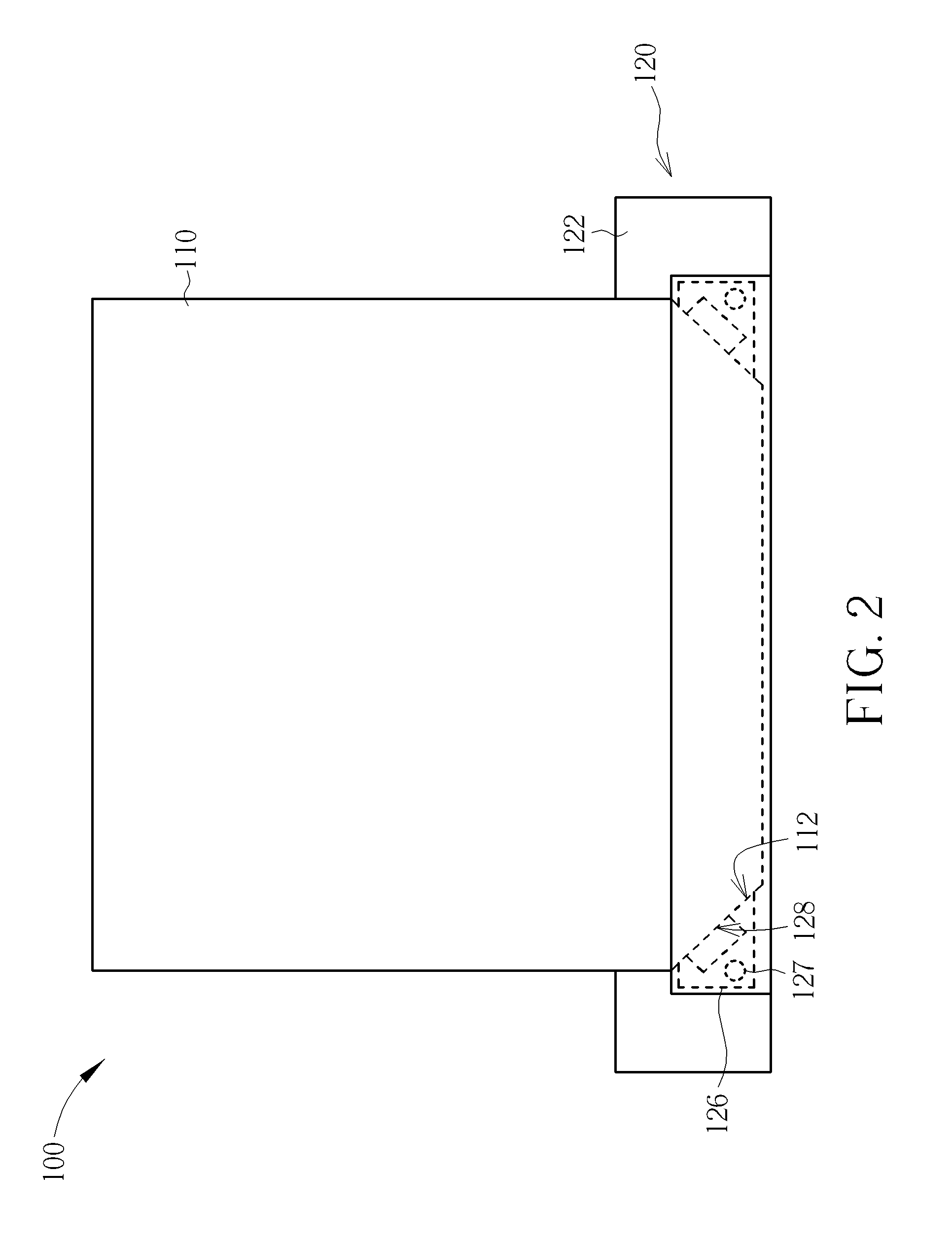
[0019]Please refer to FIG. 1 to FIG. 4 together. FIG. 1 is a diagram showing an explosive view of a backlight module of an embodiment of the present invention. FIG. 2 is a diagram showing assembly of the backlight module of the embodiment of the present invention. FIG. 3 is a diagram showing a side view of a reflection cover of the backlight module. FIG. 4 is a diagram showing a light emitting module of the backlight module. As shown in figures, the backlight module 100 comprises a light guide plate 110 and a light source structure 120. In the embodiment, the light guide plate 110 comprises two light incident surfaces 112 respectively arranged at two corners of the light guide plate 110. The light guide plate 110 further comprises a connecting surface 114 for connecting the two light incident surfaces 122. The light source structure 120 is arranged at one side of the light guide plate 110 for being combined with the light guide plate 110. The light source structure 120 comprises a r...


PUM

PropertyMeasurementUnit
Lengthaaaaaaaaaa
Heightaaaaaaaaaa
Lightaaaaaaaaaa

Abstract

A backlight module includes a light guide plate with at least one light incident surface, and a light source structure arranged at a side of the light guide plate. The light source structure includes a reflection cover and at least one light emitting module. At least one positioning pin is arranged on the reflection cover. The at least one light emitting module is installed on the reflection cover and corresponding to the at least one light incident surface. The at least one light emitting module is fixed on the positioning pin in a rotatable manner, such that the at least one light emitting module can rotate around the positioning pin as an axis when the reflection cover is combined with the light guide plate, so as to allow the at least one light emitting module facing the at least one light incident surface.

Description

BACKGROUND OF THE INVENTION[0001]1. Field of the Invention[0002]The present invention relates to a backlight module and an assembly method thereof, and more particularly, to a backlight module and an assembly method capable of improving efficiency of the backlight module.[0003]2. Description of the Prior Art[0004]Since a liquid crystal display panel can not emit light by itself, a liquid crystal display device must utilize a backlight module to provide light to the liquid crystal display panel for displaying images. Generally, the backlight module is arranged behind the liquid crystal display panel, and utilizes combinations of light sources and optical components (such as light guide plate, optical diffuser film, optical reflection film) to provide a uniform light source with high brightness to the liquid crystal display panel. The liquid crystal display panel then controls pixels to display corresponding colors according to display data for displaying images. Base on location of t...

Claims


Application Information

Patent Timeline
IPC IPC(8): F21V7/00F21V17/10F21V8/00
CPCY10T29/49895F21S8/00F21V19/02G02B6/0091F21V7/00G02F1/133605G02F1/1335F21V17/10Y10T29/49799G02B6/0031
Inventor WANG, CHENG-YUTSAI, CHENG-MIN
Owner AU OPTRONICS CORP
Why Eureka
Try Eureka