
Acoustic signal processing device, acoustic signal processing method, and acoustic signal processing program

Active Publication Date: 2014-01-30
HONDA MOTOR CO LTD +1
View PDF3 Cites 34 Cited by
  • Summary
  • Abstract
  • Description
  • Claims
  • Application Information

AI Technical Summary

Benefits of technology

The invention provides an acoustic signal processing device, method, and program that effectively reduce noise using a small amount of prior information. It has several technical effects, such as reducing the amount of processing needed to calculate a filter coefficient, avoiding degeneration between channels regarding a delay sum element to reduce noise, reducing noise with respect to an acoustic signal based on a sound wave from a specific direction, and significantly reducing noise from a specific direction with a smaller amount of computation.

Problems solved by technology

In ANC, there is a problem in that a filter coefficient which is obtained by operating the adaptive filter does not necessarily become a comprehensive optimum solution and suppresses target sound as well as noise.

Method used


Image

  • Acoustic signal processing device, acoustic signal processing method, and acoustic signal processing program
  • Acoustic signal processing device, acoustic signal processing method, and acoustic signal processing program
  • Acoustic signal processing device, acoustic signal processing method, and acoustic signal processing program

Examples


first embodiment

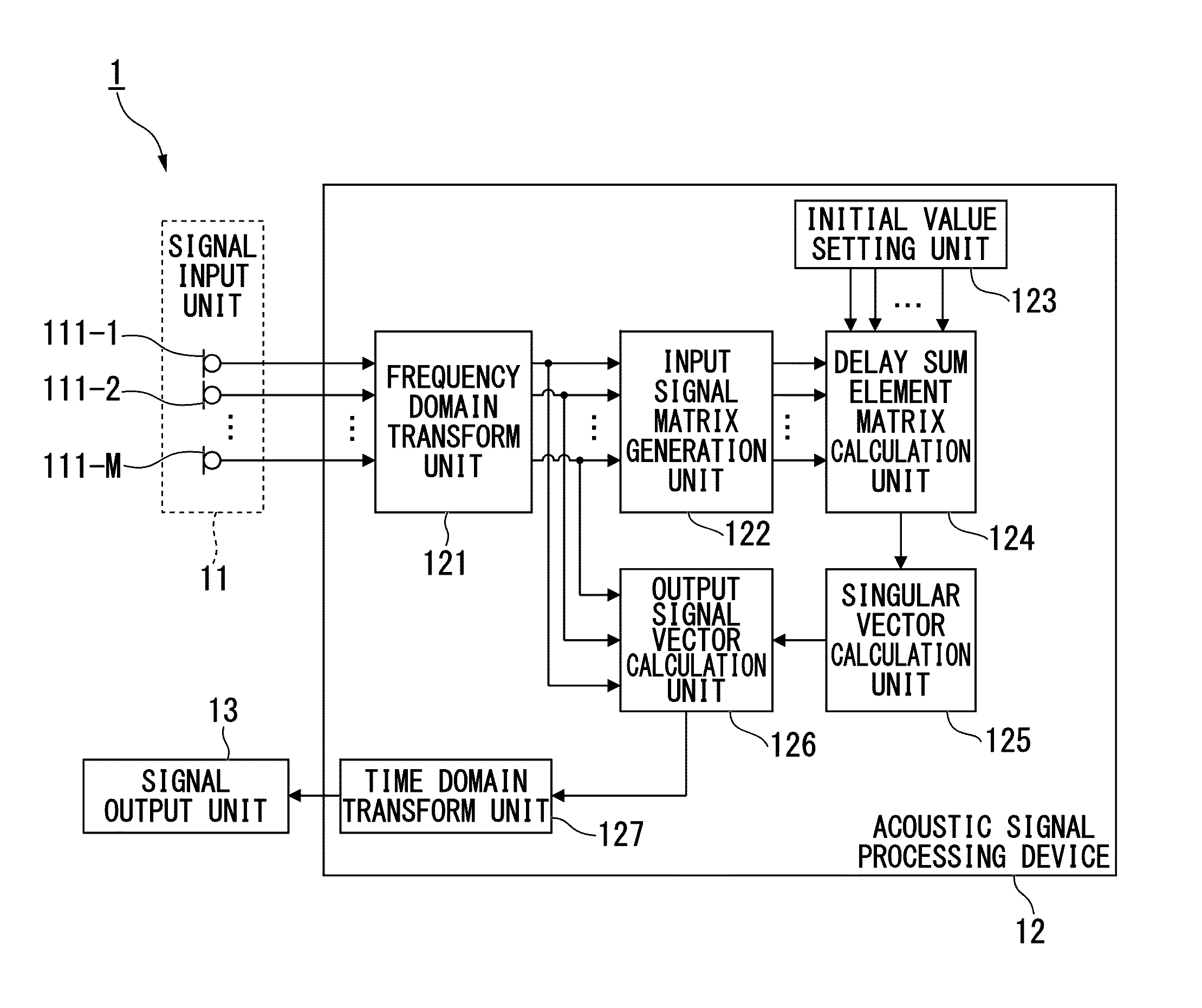
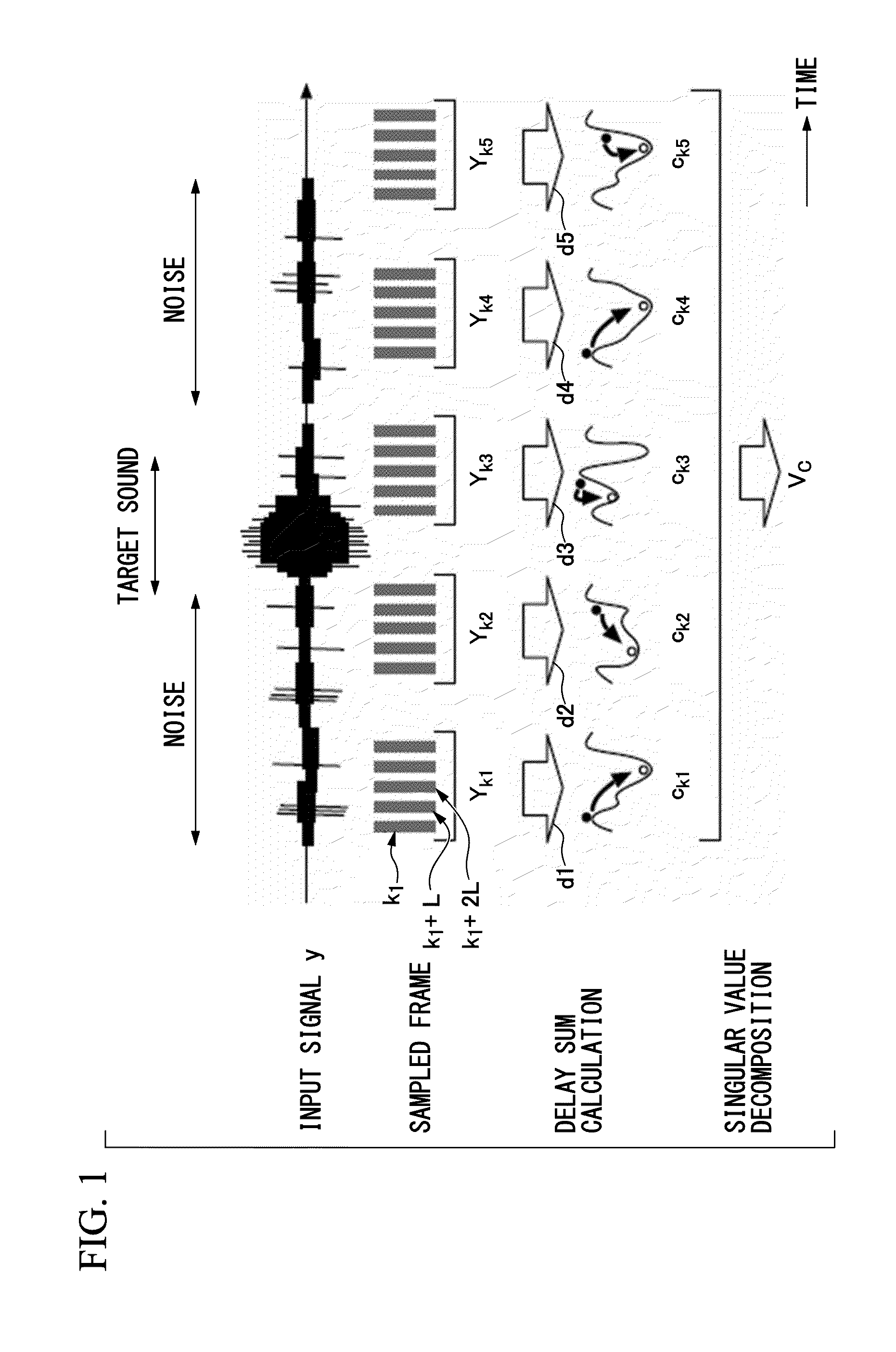
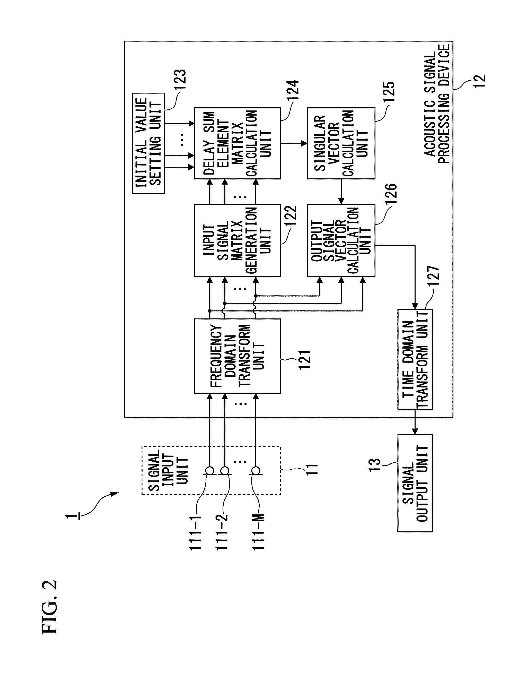
[0040]Acoustic signal processing according to this embodiment defines a delay sum of signals of a plurality of channels in a frequency domain signal obtained by transforming a multichannel acoustic signal to a frequency domain for each channel, and calculates a delay sum element matrix having delay sum elements configured to minimize the magnitude of the residual. Then, a unitary matrix or a singular vector obtained by performing singular value decomposition on the delay sum element matrix is multiplied to an input signal vector based on the input acoustic signal to calculate an output signal vector. In the acoustic signal processing, when calculating delay sum elements, computation is recursively performed so as to give a random number to an initial value and to minimize the magnitude of the residual.

[0041]The outline of the acoustic signal processing according to this embodiment will be described referring to FIG. 1.

[0042]FIG. 1 is a conceptual diagram of the acoustic signal proce...

second embodiment

[0092]Next, a second embodiment of the invention will be described.

[0093]The configuration of an acoustic signal processing system 2 according to this embodiment will be described while the same configuration and processing are represented by the same reference numerals.

[0094]FIG. 4 is a schematic view showing the configuration of the acoustic signal processing system 2 according to this embodiment.

[0095]The acoustic signal processing system 2 includes a signal input unit 11, an acoustic signal processing device 22, a signal output unit 13, and a direction output unit 23.

[0096]The acoustic signal processing device 22 includes a direction estimation unit 221 in addition to a frequency domain transform unit 121, an input signal matrix generation unit 122, an initial value setting unit 123, a delay sum element matrix calculation unit 124, a singular vector calculation unit 125, an output signal vector calculation unit 126, and a time domain transform unit 127.

[0097]The direction estima...

experimental example

[0122]Next, an experimental example which is carried out by operating the acoustic signal processing system 2 according to this embodiment will be described. In the experiment, a single noise source 31 arranged in an experimental laboratory emits noise, and a single sound source 32 emits target sound. An acoustic signal in which recorded noise and target sound are mixed is input from the signal input unit 11, and the acoustic signal processing system 2 is operated.

[0123]An arrangement example of the signal input unit 11, the noise source 31, and the sound source 32 will be described.

[0124]FIG. 6 is a plan view showing an arrangement example of the signal input unit 11, the noise source 31, and the sound source 32.

[0125]A horizontally long rectangle shown in FIG. 6 represents an inner wall surface of the experimental laboratory. The size of the experimental laboratory is a rectangular parallelepiped of 3.5 m vertical, 6.5 m horizontal, and 2.7 m height. The noise source 31 is substan...


PUM


Abstract

An acoustic signal processing device includes a frequency domain transform unit configured to transform an acoustic signal to a frequency domain signal for each channel, a filter coefficient calculation unit configured to calculate at least two sets of filter coefficients of a filter for each section having a predefined number of frames with respect to a sampled signal obtained by sampling the frequency domain signal transformed by the frequency domain transform unit for each frame such that the magnitude of a residual calculated based on a filter compensating for the difference in transfer characteristics between the channels of the acoustic signal is minimized, and an output signal calculation unit configured to calculate an output signal of a frequency domain based on the frequency domain signal transformed by the frequency domain transform unit and at least two sets of filter coefficients calculated by the filter coefficient calculation unit.

Description

CROSS REFERENCE TO RELATED APPLICATIONS[0001]Priority is claimed on Japanese Patent Application No. 2012-166276, filed on Jul. 26, 2012, the contents of which are entirely incorporated herein by reference.BACKGROUND OF THE INVENTION[0002]1. Field of the Invention[0003]The present invention relates to an acoustic signal processing device, an acoustic signal processing method, and an acoustic signal processing program.[0004]2. Description of Related Art[0005]A sound source separation technique for separating a component by a certain sound source, a component by another sound source, and a component by noise from a recorded acoustic signal has been suggested. For example, in a sound source direction estimation device described in Japanese Unexamined Patent Application, First Publication No. 2010-281816, in order to select sound to be erased or focused, the sound source direction estimation device includes acoustic signal input means for inputting an acoustic signal, and calculates a co...

Claims


Application Information

Patent Timeline
IPC IPC(8): G10K11/175
CPCG10K11/175G10L21/0272
Inventor NAKADAI, KAZUHIROKUMON, MAKOTOODA, YASUAKI
Owner HONDA MOTOR CO LTD
Learn More