
System and method for identification of conductor surface roughness model for transmission lines

a technology of conductor surface roughness and identification method, which is applied in the direction of instruments, wave/particle radiation means, design optimisation/simulation, etc., can solve the problems of signal degradation, difficult to define the model parameters for any particular case, and the manufacturers of pcb copper foils do not provide electrical characterization data for pcb copper roughness

Inactive Publication Date: 2014-01-30
SIMBERIAN
View PDF2 Cites 9 Cited by
  • Summary
  • Abstract
  • Description
  • Claims
  • Application Information

AI Technical Summary

Benefits of technology

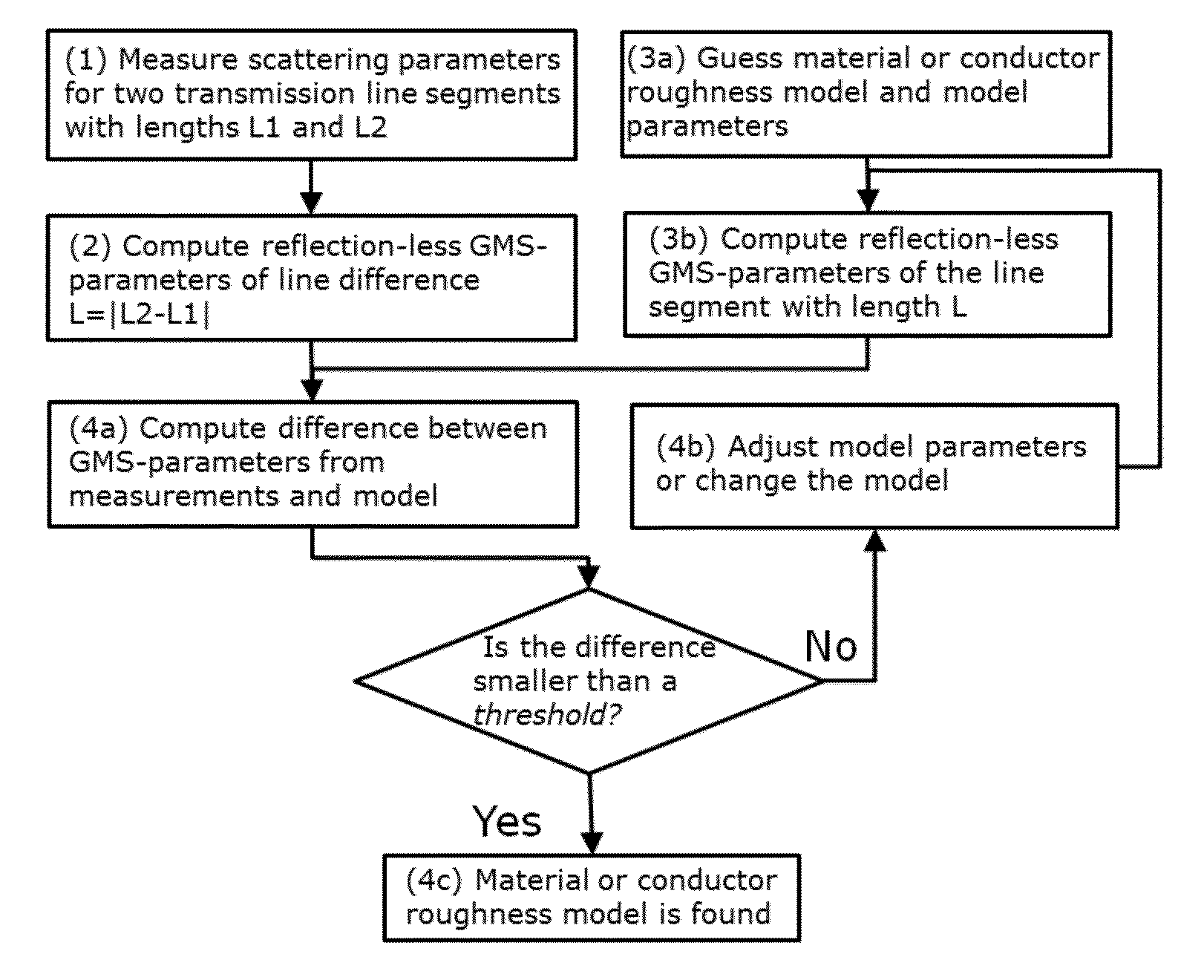
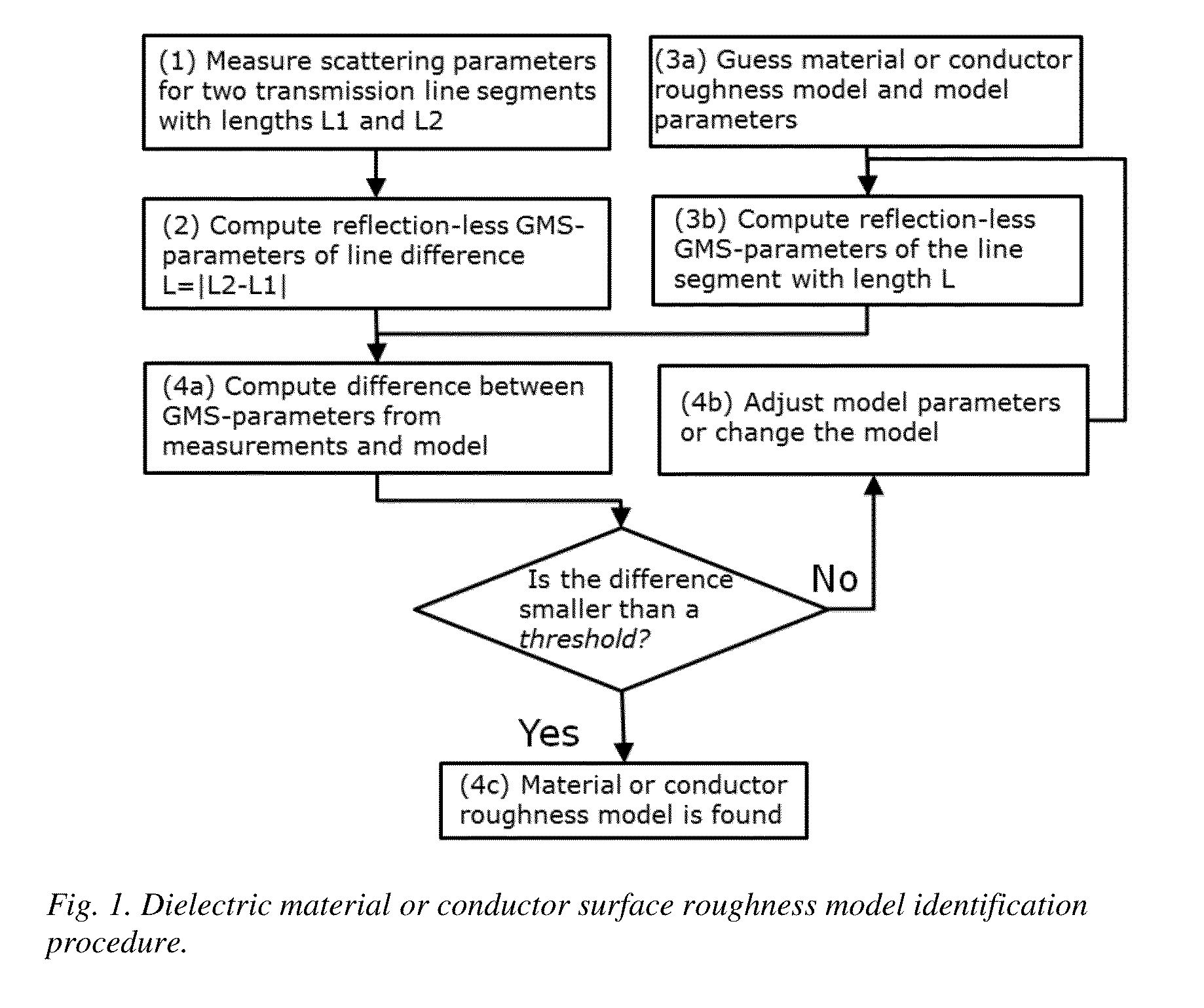
The invention is a method for analyzing the properties of transmission lines using a 3D full-wave electromagnetic analysis. It can account for conductor and dielectric losses, as well as dispersion and surface roughness of the conductor. The method is less sensitive to measurement noise and geometrical differences between samples. It can be used with different types of transmission lines and can provide a more accurate model of the line's behavior. The method involves measuring scattering parameters for two transmission line segments with different lengths and cross-sectional geometry. The segments can be of different types and can be connected using coaxial connectors or conductive probe pads. The method can be implemented using a computer program. The invention can help improve the design and performance of transmission lines.

Problems solved by technology

Conductor surface roughness causes signal degradation.
PCB copper foil manufacturers do not provide data for the electrical characterization of the copper roughness.
In practice, all roughness correction coefficients were validated with experiments, but still exhibit one common problem—it is difficult to define the model parameters for any particular case.
Measurement results obtained using expensive equipment are typically required to define parameters for a particular model.
That value is typically available from the copper or laminate manufacturer, but the model is limited to certain types of copper as discussed earlier.
The authors of [3] and [4] also pointed out that measurements with a profilometer or from micro-photographs of cross-sections may be misleading in predicting the effect of the roughness topography.
It has been shown that the profilometer data or micro-photography may not provide sufficient resolution to capture all the peculiarities of the rough surface to build any model [9].

Method used


Image

  • System and method for identification of conductor surface roughness model for transmission lines
  • System and method for identification of conductor surface roughness model for transmission lines
  • System and method for identification of conductor surface roughness model for transmission lines

Examples


Embodiment Construction

Invention Components

[0027]1) Network analyzer such as Vector Network Analyzer (VNA) or Time-Domain Network Analyzer—an apparatus that measures complex scattering parameters (S-parameters) of a multiport structure.[0028]2) At least two transmission line segments with substantially identical cross-section and conductor roughness profile. One or multi-conductor strip or microstrip line, coplanar waveguide or any other line type can be used. Two segments must have different lengths—one segment is shorter and another is longer. Geometry of the cross-section and models for all line dielectrics must be known (separately identified or from specifications). Both segments are equipped with either coaxial connectors or conductive probe pads to measure S-parameters over a given frequency range.[0029]3) Calculator (first engine) of non-reflective or generalized modal S-parameters of line segment difference from two sets of S-parameters measured for two line segments.[0030]4) Calculator (second e...


PUM


Abstract

A system and method for identification of conductor surface roughness model associated with a transmission line conductor is proposed. A network analyzer measures scattering parameters over a specified frequency band for at least two line segments of different length and substantially identical cross-section with investigated rough conductors. A first engine determines non-reflective (generalized) modal scattering parameters of the difference segment based on the measured scattering parameters of two line segments. A second engine computes generalized modal scattering parameters of the line difference segment by solving Maxwell's equations for geometry of the line cross-section with a given conductor surface roughness model. A third engine performs optimization by changing conductor surface roughness model parameters and model type until the computed and measured generalized modal scattering parameters match. The model that produces generalized modal S-parameters closest to the measured is the final conductor surface roughness model.

Description

CROSS-REFERENCE TO RELATED APPLICATIONS[0001]The current application is a continuation-in-part of application Ser. No. 13 / 009,541 filed on Jan. 19, 2011 which claims a priority to 61 / 296,237 filed on Jan. 19, 2010.FIELD OF INVENTION[0002]This invention relates generally to system and method for identification of conductor surface roughness model associated with a transmission line conductor. The system will make use of a network analyzer or equivalent instruments, two transmission line segments, and three engines used for calculations.BACKGROUND OF THE INVENTION[0003]During the manufacturing process of printed circuit boards (PCBs) and some types of packages, copper foils are treated to increase surface roughness and improve adhesion to dielectrics in order to avoid delamination. Conductor surface roughness causes signal degradation. Appropriate electrical modeling of conductor roughness on such boards is important for accurate prediction of signal degradation effects as discussed i...

Claims


Application Information

Patent Timeline
IPC IPC(8): G06F17/50
CPCG06F17/5018G01B15/08G06F30/367G06F30/23
Inventor SHLEPNEV, YURIY
Owner SIMBERIAN
Learn More