Rigid-flexible substrate and method for manufacturing the same

Active Publication Date: 2014-02-06
MURATA MFG CO LTD
View PDF9 Cites 17 Cited by
  • Summary
  • Abstract
  • Description
  • Claims
  • Application Information

AI Technical Summary

Benefits of technology

[0018]According to various preferred embodiments of the present invention, by causing a portion of a thermoplastic resin constituting the rigid portion to flow toward the flexible portion, a boundary between the rigid portion and the flexible portion has a smooth shape without requiring special machining. Therefore, flex resistance and rupture strength of a boundary portion between the flexible portion and the rigid portion is greatly improved, while preventing cracking, breaking or peeli

Problems solved by technology

In this case, there has been a problem in that a crack, peel-off, or the like is likely to occur at a junction between the rigid portion and the flexible portion.
Further, in the method described in Japanese Patent Laid-Open No. 2004-319962, the printed wiring board is required to ha

Method used


Image

  • Rigid-flexible substrate and method for manufacturing the same
  • Rigid-flexible substrate and method for manufacturing the same
  • Rigid-flexible substrate and method for manufacturing the same

Examples


embodiment 1

Preferred Embodiment 1

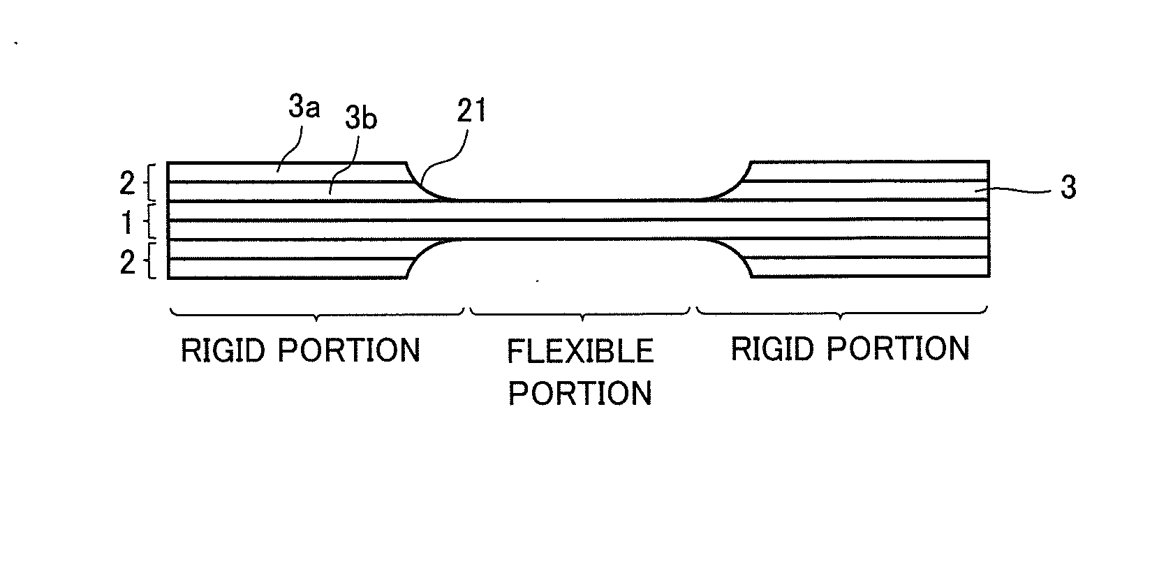
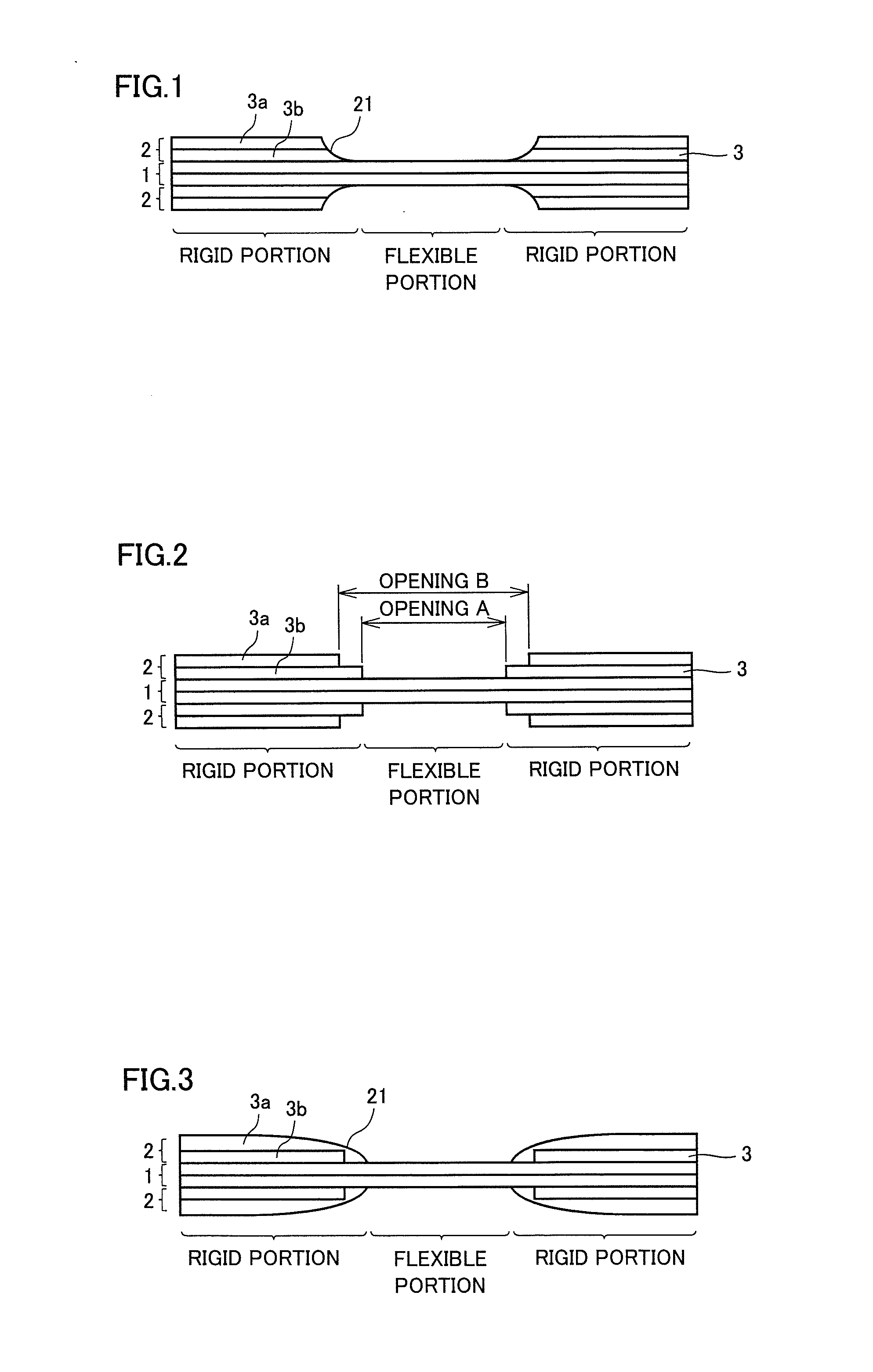
[0039]In the present preferred embodiment, a description will be given of a rigid-flexible substrate in a case where, of the plurality of thermoplastic resin sheets constituting the second resin sheet, a thermoplastic resin sheet closer to the first resin sheet has a longer length in a direction perpendicular or substantially perpendicular to a boundary surface between the flexible portion and the rigid portion, with reference to FIGS. 1 and 2. FIG. 1 is a schematic cross sectional view of a rigid-flexible substrate in Preferred Embodiment 1. FIG. 2 is a schematic cross sectional view showing the rigid-flexible substrate in Preferred Embodiment 1 in a state before lamination pressing.

[0040]As shown in FIG. 1, in the rigid-flexible substrate in the present preferred embodiment, second resin sheets 2 each including two layers of thermoplastic resin sheets 3 are laminated on a portion of both surfaces of a first resin sheet 1 including two layers of thermoplastic ...

embodiment 2

Preferred Embodiment 2

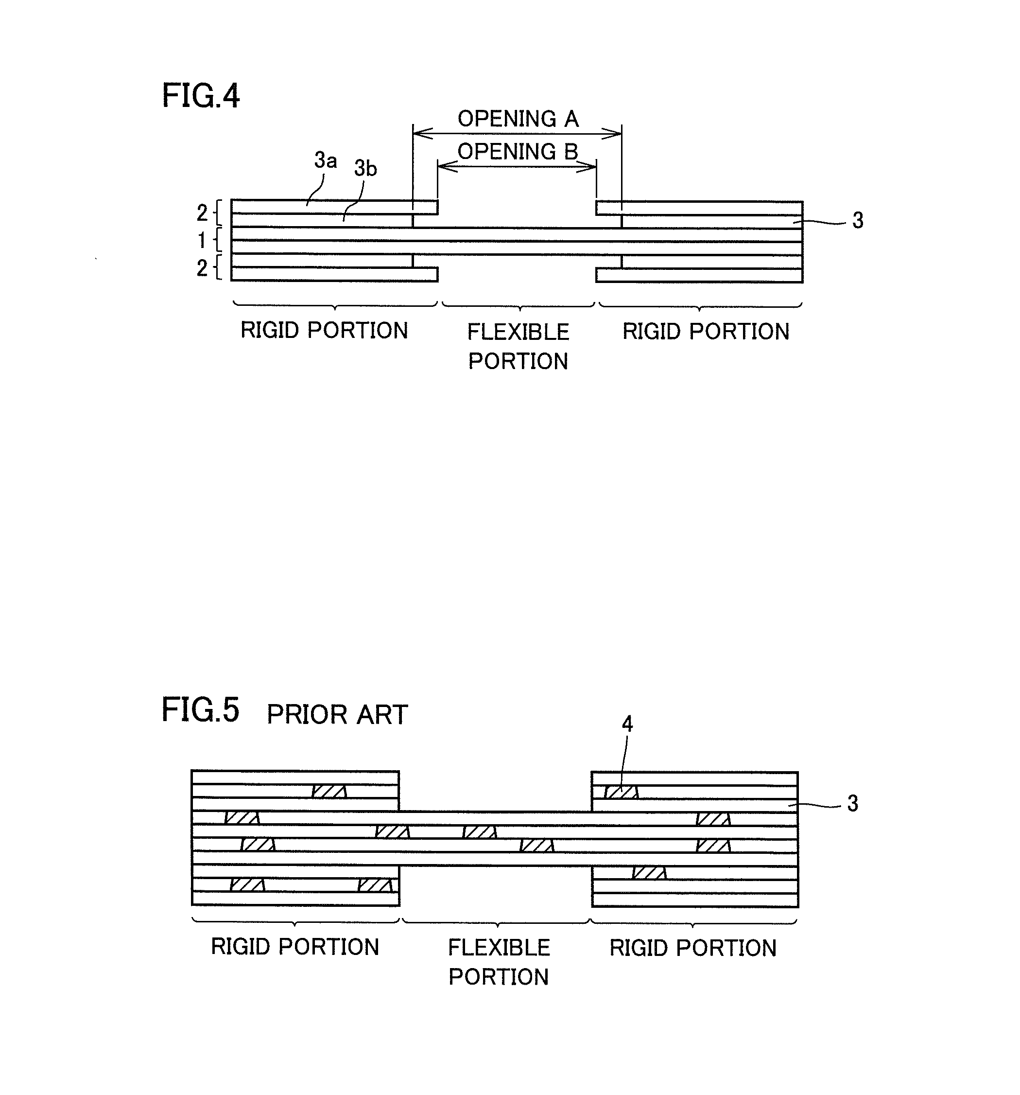
[0050]In the present preferred embodiment, a description will be given of a rigid-flexible substrate in a case where a surface of the second resin sheet which is not in contact with the first resin sheet is entirely covered with an outermost thermoplastic resin sheet constituting the second resin sheet, with reference to FIGS. 3 and 4. FIG. 3 is a schematic cross sectional view of a rigid-flexible substrate in Preferred Embodiment 2. FIG. 4 is a schematic cross sectional view showing the rigid-flexible substrate in Preferred Embodiment 2 in a state before lamination pressing. It is noted that, regarding the content identical to that in Preferred Embodiment 1, the description thereof will not be repeated partially.

[0051]As shown in FIG. 3, in the rigid-flexible substrate in the present preferred embodiment, second resin sheets 2 each including two layers of thermoplastic resin sheets 3 are laminated on a portion of both surfaces of first resin sheet 1 including ...


PUM

PropertyMeasurementUnit
Lengthaaaaaaaaaa
Flexibilityaaaaaaaaaa
Stiffnessaaaaaaaaaa

Abstract

A rigid-flexible substrate includes a plurality of rigid portions, and a flexible portion connecting the plurality of rigid portions and including a portion of a first resin sheet including at least one layer of a thermoplastic resin sheet, the rigid portions including a portion of the first resin sheet other than the flexible portion, and a second resin sheet including a plurality of thermoplastic resin sheets laminated on one surface or both surfaces of the portion of the first resin sheet other than the flexible portion, and a tapered portion is provided at an end edge of the second resin sheet on a side close to the flexible portion, and a thickness of the tapered portion in a direction in which the second resin sheet is laminated decreases toward the flexible portion and is substantially 0 at a position in contact with the flexible portion.

Description

BACKGROUND OF THE INVENTION[0001]1. Field of the Invention[0002]The present invention relates to a rigid-flexible substrate and a method for manufacturing the same.[0003]2. Description of the Related Art[0004]In recent years, so-called printed substrates having a conductor wire layer formed on a surface of a thermoplastic resin sheet have been applied to packages incorporating circuit boards and semiconductor elements, and the like. In addition, as more layers of wires are laminated, conductor wire layers between different layers are electrically connected by a via conductor.[0005]Further, rigid-flexible substrates formed by integrating a flexible printed substrate (flexible portion) and a rigid substrate (rigid portion) have been known. The rigid-flexible substrate generally has advantages in that it is excellent in component mounting properties because its rigid portion has rigidity equal to that of the rigid substrate, and that it can be incorporated into electronic equipment in ...

Claims


Application Information

Patent Timeline
IPC IPC(8): H05K1/02
CPCH05K1/0278H05K1/028H05K3/4691H05K2201/2009H05K2201/0129H05K2201/09827H05K2201/09845Y10T428/24488
Inventor OTSUBO, YOSHIHITOYOSHIKAWA, TAKAYOSHITAKEZAWA, AKINORI
Owner MURATA MFG CO LTD
Why Eureka
Try Eureka