
A microfluidic cell and a spin resonance device for use therewith

a microfluidic cell and spin resonance technology, which is applied in the field of microfluidic cells and spin resonance devices for use therewith, can solve the problems of/or devices, unsuitable devices for integration into small, portable analytical devices, and insufficient sensitive to resolve precise chemical shift information

Active Publication Date: 2014-02-06
ELEMENT SIX LTD
View PDF0 Cites 20 Cited by
  • Summary
  • Abstract
  • Description
  • Claims
  • Application Information

AI Technical Summary

Benefits of technology

The present invention, which is based on a patent application, describes a microfluidic cell with a sensor that uses a diamond material with quantum spin defects. The sensor is located near the microfluidic channel in the cell. The cell can be connected to a spin resonance device that includes a first and a second field generator for manipulating the quantum spins and the spin defects, respectively. The device also includes a light source and a detector for detecting the emitted light. The invention makes possible the analysis of fluid samples for spin resonance data. The technical effects of this invention include improved accuracy and sensitivity for detecting and manipulating quantum spins in a microfluidic environment, which can be used for analysis of fluid samples.

Problems solved by technology

There are several problems associated with integrating an NMR device into a portable analytical device comprising a microfluidic cell as discussed below.
However, such pickup coils are very insensitive and thus relatively large sample volumes and a high magnetic field strength, typically produced by a superconducting magnet, are used to improve signal strength and increase the ability to resolve NMR chemical shifts.
This results in standard NMR devices being very large and unsuitable for integration into a small, portable analytical device and / or a device which uses small sample volumes.
However, again these devices are unsuitable for integration into small, portable analytical devices as SQUIDs require cryogenic cooling and alkali-vapour atomic magnetometers require a heated vapour cell.
One problem with the arrangement described in WO 2009 / 046350 is that although magnetoresistive sensors can be made small for incorporation into a microfluidic cell, they are not sufficiently sensitive to resolve precise chemical shift information without the application of a strong (>1 Tesla) homogeneous field.
However, it would appear from the teachings of WO 2009 / 046350 that a magetoresistive sensor is not sufficiently sensitive to facilitate such miniaturization when precise chemical shift information is desired due to the requirement for a strong homogeneous magnetic field to resolve such information.

Method used


Image

  • A microfluidic cell and a spin resonance device for use therewith
  • A microfluidic cell and a spin resonance device for use therewith
  • A microfluidic cell and a spin resonance device for use therewith

Examples


example synthesis

[0112]A synthetic type Ib HPHT diamond plate with a pair of approximately parallel major faces within approximately 5° of (001) was selected. The plate was fabricated into a square substrate suitable for homoepitaxial synthesis of single crystal CVD diamond material by a process including the following steps:

i) laser cutting of the substrate to produce a plate with all edges;

ii) lapping and polishing the major surface upon which growth is to occur, the lapped and polished part having dimensions about 3.6 mm×3.6 mm by 535 μm thick, with all faces {100}.

[0113]The defect level at or below the substrate surface is minimised by careful preparation of the substrate as disclosed in EP 1 292 726 and EP 1 290 251. It is possible to reveal the defect levels being introduced by this processing by using a revealing plasma etch. It is possible routinely to produce substrates in which the density of defects measurable after a revealing etch is dependent primarily on the material quality and is b...


PUM


Abstract

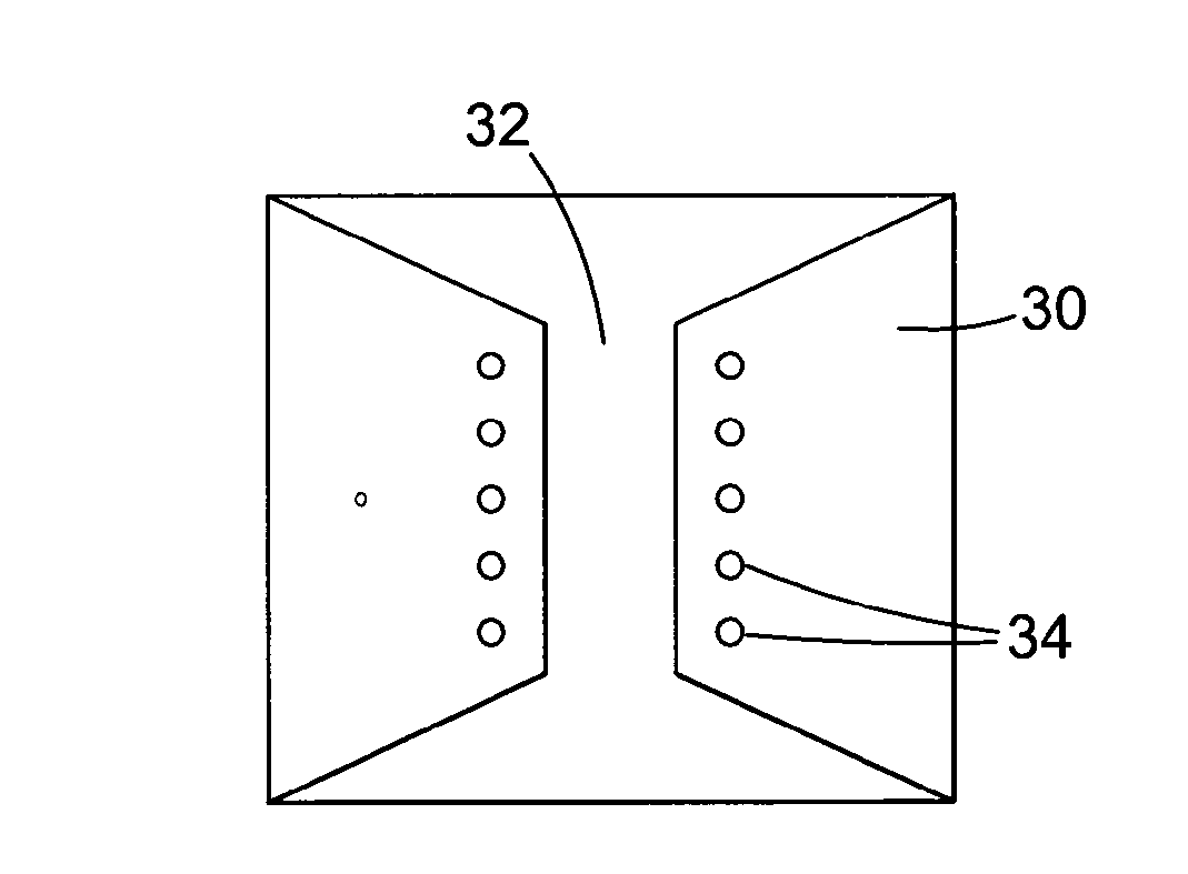
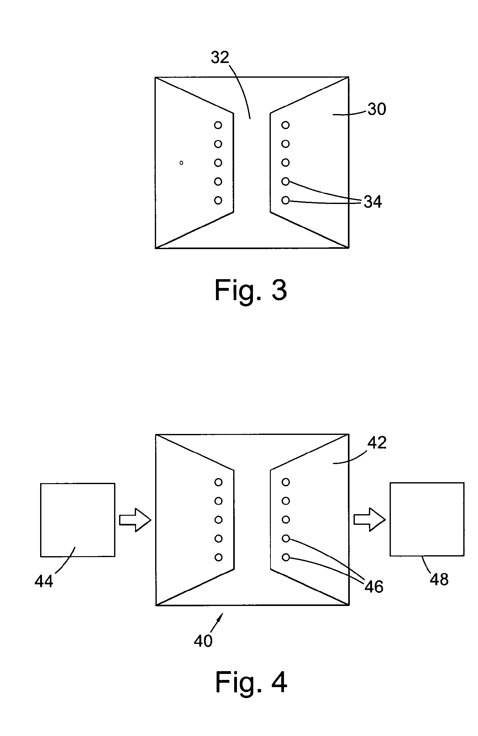
A microfluidic cell comprising: a microfluidic channel (32) for receiving a fluid sample; and a sensor (30) located adjacent the microfluidic channel; wherein the sensor comprises a diamond material comprising one or more quantum spin defects (34). In use, a fluid sample is loaded into the microfluidic cell and the fluid is analysed via magnetic resonance using the quantum spin defects.

Description

FIELD OF INVENTION[0001]The present invention relates to a microfluidic cell and a spin resonance device for use therewith.BACKGROUND OF INVENTION[0002]A microfluidic cell generally comprises one or more channels with at least one dimension equal to or less than 1 mm, more particularly in the range 100 nm to 1 mm. In use, a fluid sample is introduced into the one or more channels of the cell and analysed therein. The analysis may involve, for example, using one or more reagents disposed within the cell and arranged to react with at least a portion of the sample introduced into the cell. As such, microfluidic cells can provide integrated, portable analytical devices thereby eliminating time consuming laboratory analysis procedures.[0003]It is also known to couple microfluidic cells with other devices such as protein arrays and mass spectrometers to further enhance analytical functionality. A review of integrated microfluidic technology is provided by D. Erickson and Dongqing Li in th...

Claims


Application Information

Patent Timeline
IPC IPC(8): B01L3/00G01R33/30
CPCB01L3/502707B01L2300/0663G01R33/24G01R33/302G01R33/323G01R33/465G01R33/60B01L3/502715B01L3/00
Inventor TWITCHEN, DANIEL JAMESMARKHAM, MATTHEW LEE
Owner ELEMENT SIX LTD
Learn More