
System and method to perform scan testing using a pulse latch with a blocking gate

Active Publication Date: 2014-02-06
QUALCOMM INC
View PDF1 Cites 5 Cited by
  • Summary
  • Abstract
  • Description
  • Claims
  • Application Information

AI Technical Summary

Benefits of technology

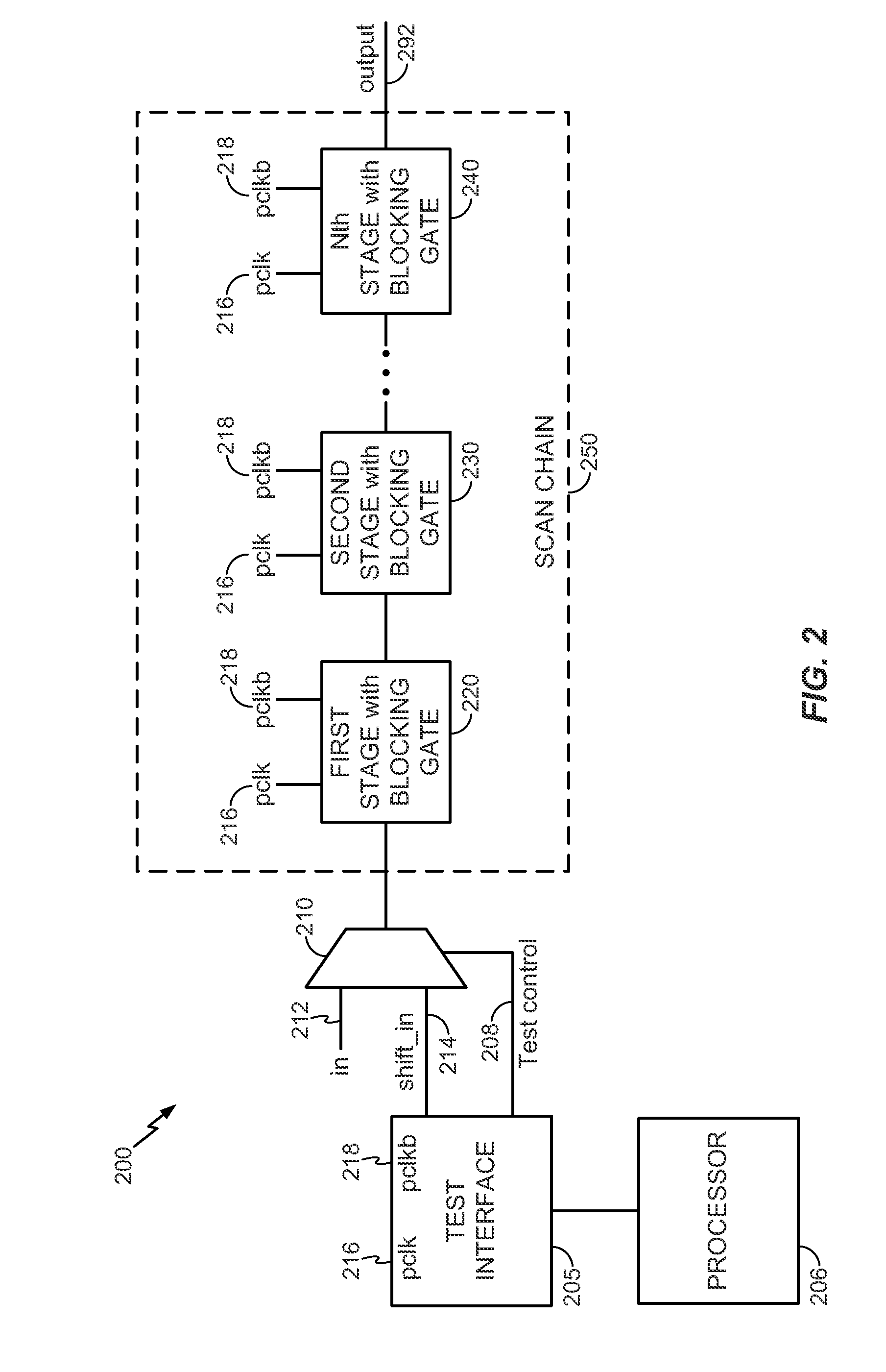
The patent is about a device called a scan chain that has a series of stages that each include a pulse latch and a blocking gate. These stages allow data to be received and propagated from one stage to the next using a pulse clock signal. The use of clocked gates, specifically transmission gates, can help reduce a race condition that can occur in the scan chain. This design also reduces the number of poly pitches which simplifies the process of fabricating the device. The technical effect of this patent is to provide a more reliable and efficient scan chain device with improved data transmission and reduced latency.

Problems solved by technology

This implementation results in approximately 18 poly pitches (e.g., a designation of an area of an IC based on a number of polysilicon lines) per scan register, which impedes reduction of the size of an IC.
However, using pulse latches rather than scan registers may result in a race condition due to timing variances within and between each pulse latch.
The addition of the delay gates increases the size and cost of the scan chain.

Method used


Image

  • System and method to perform scan testing using a pulse latch with a blocking gate
  • System and method to perform scan testing using a pulse latch with a blocking gate
  • System and method to perform scan testing using a pulse latch with a blocking gate

Examples


Embodiment Construction

[0022]Particular embodiments of the present disclosure are described further with reference to the drawings. In the description, common features are designated by common reference numbers throughout the drawings.

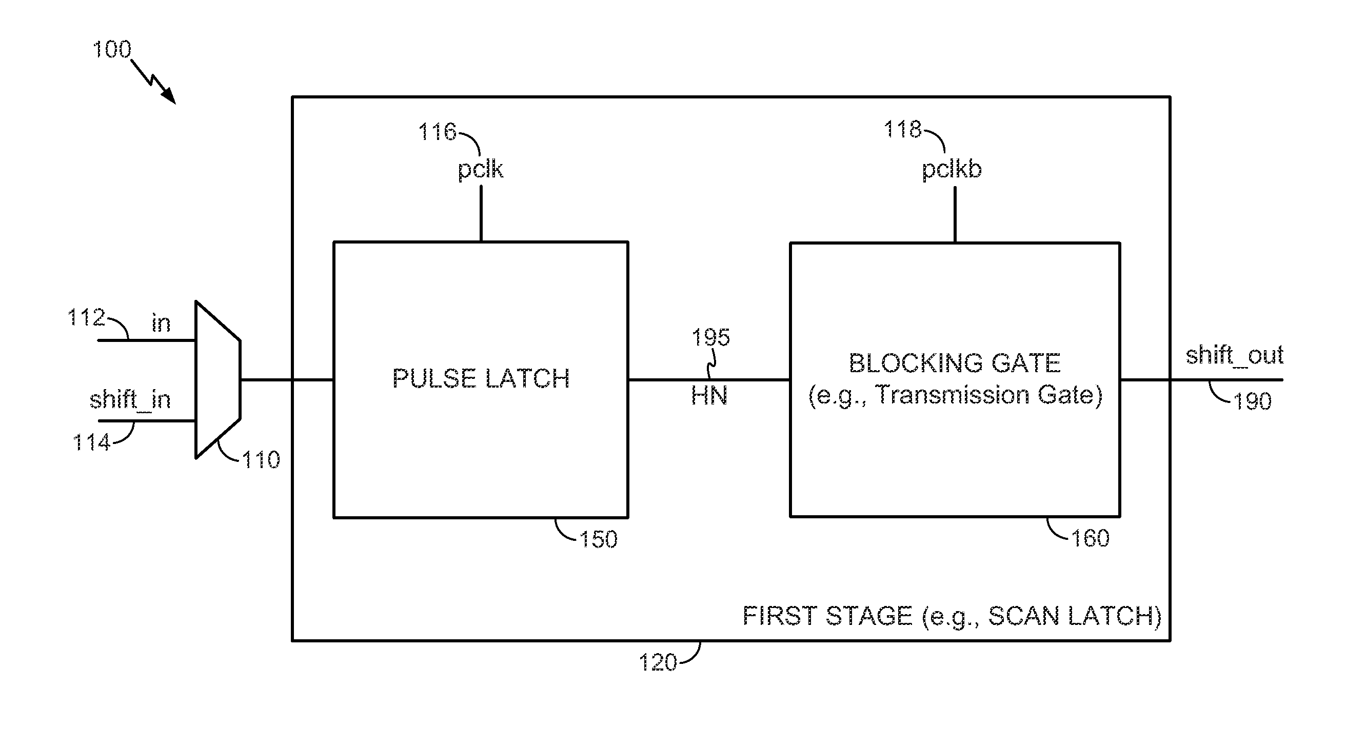
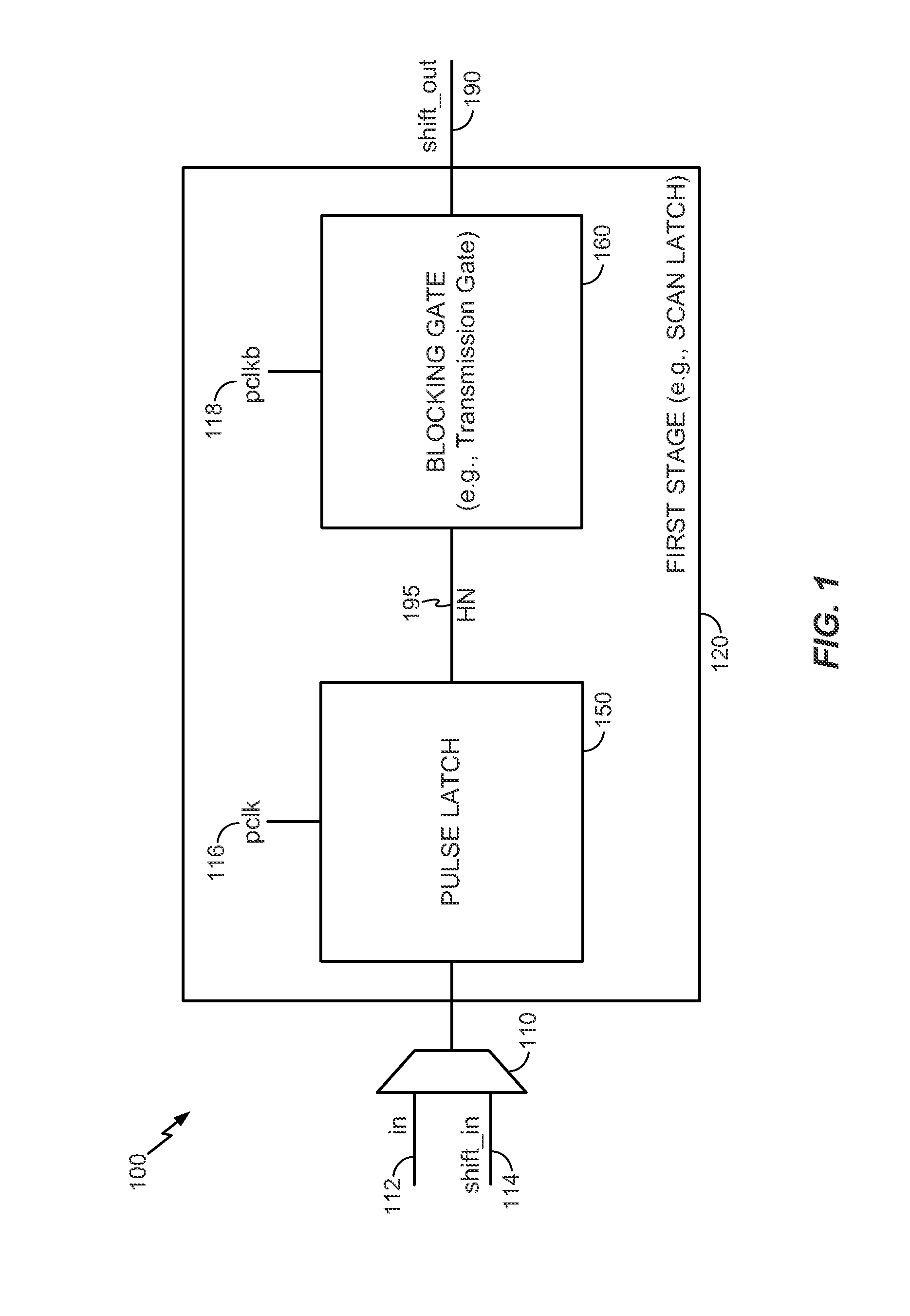
[0023]Referring to FIG. 1, a particular illustrative embodiment of a system including a first stage of a scan chain device is disclosed and generally designated 100. The system 100 may include a multiplexer 110 coupled to a first stage 120 (e.g., a scan latch) of the scan chain. The first stage 120 includes a pulse latch 150 and a blocking gate 160. The first stage 120 of the scan chain having the blocking gate 160 may enable on-chip testing of a memory cell array that includes a plurality of pulse latches coupled in series.

[0024]The multiplexer 110 may receive input data 112 and / or shift_in input data 114. An output of the multiplexer 110 may be provided to the first stage 120. The first stage 120 may be one of a plurality of stages of the scan chain and may be directly cou...


PUM


Abstract

A system and method to perform scan testing using a pulse latch with a blocking gate is disclosed. In a particular embodiment, a scan latch includes a pulse latch operable to receive data while a pulse clock signal has a first logical clock value and a blocking gate coupled to an output of the pulse latch. The blocking gate is operable to propagate the data from the output of the pulse latch while the pulse clock signal has a second logical clock value.

Description

I. FIELD[0001]The present disclosure is generally related to memory devices and more specifically to scan chains.II. DESCRIPTION OF RELATED ART[0002]Advances in technology have resulted in smaller and more powerful computing devices. For example, there currently exist a variety of portable personal computing devices, including wireless computing devices, such as portable wireless telephones, personal digital assistants (PDAs), and paging devices that are small, lightweight, and easily carried by users. More specifically, portable wireless telephones, such as cellular telephones and internet protocol (IP) telephones, can communicate voice and data packets over wireless networks. Further, many such wireless telephones include other types of devices that are incorporated therein. For example, a wireless telephone can also include a digital still camera, a digital video camera, a digital recorder, and an audio file player. Also, such wireless telephones can process executable instructio...

Claims


Application Information

Patent Timeline
IPC IPC(8): H03K3/356G06F17/50
CPCG06F17/5045H03K3/356G11C29/32G06F30/30
Inventor NARAYANAN, VENKATASUBRAMANIANBELLUR, KASHYAP R.
Owner QUALCOMM INC
Learn More