Llc converter with dynamic gain transformation for wide input and output range

Active Publication Date: 2014-02-06
ACLEAP POWER INC
View PDF7 Cites 41 Cited by
  • Summary
  • Abstract
  • Description
  • Claims
  • Application Information

AI Technical Summary

Problems solved by technology

However the ever increasing efficiency requirements have pushed the limits of these topologies to the point where efficiency gains are incremental and primarily dependent upon improvements in the characteristics of the semiconductors switches.

Method used


Image

  • Llc converter with dynamic gain transformation for wide input and output range
  • Llc converter with dynamic gain transformation for wide input and output range
  • Llc converter with dynamic gain transformation for wide input and output range

Examples


Embodiment Construction

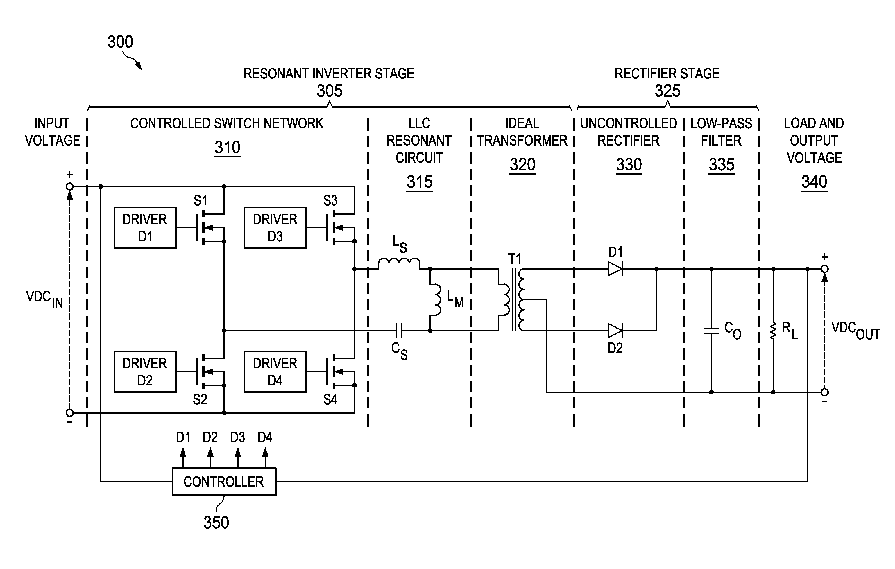
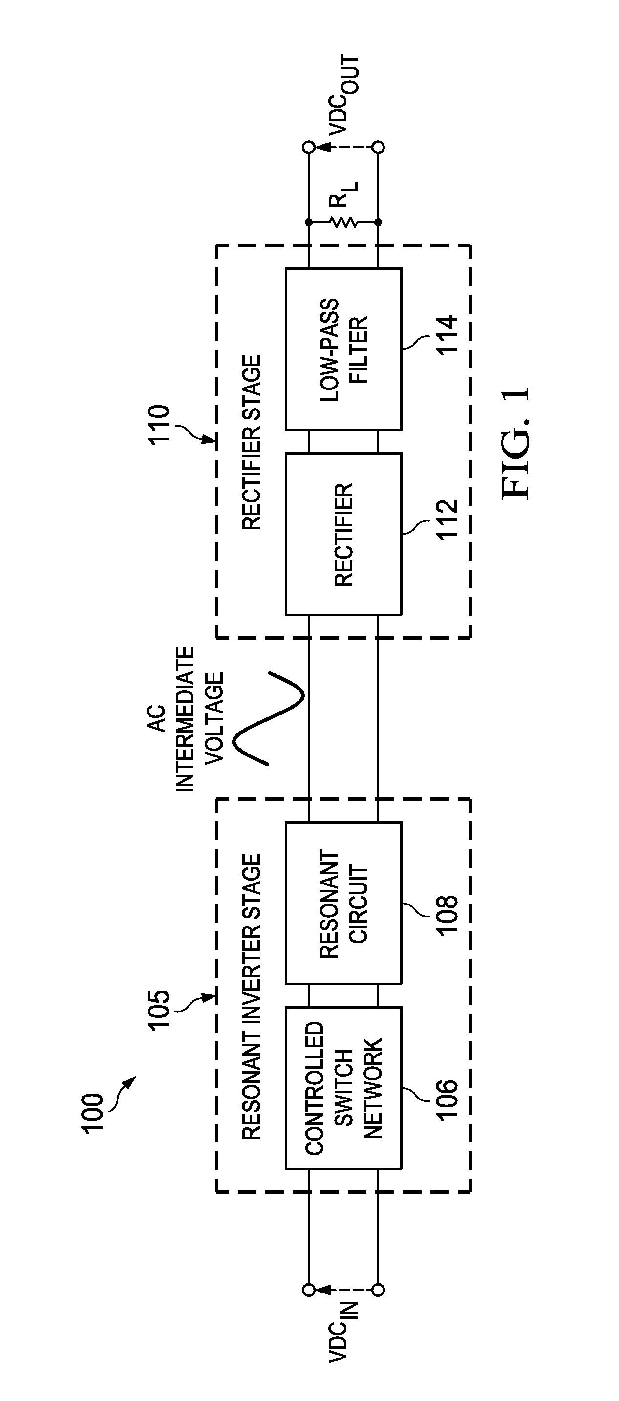
[0016]There is a renewed and broadened interest in resonant conversion topologies in AC / DC conversion systems due to market demands for higher efficiency and power density. Generally, resonant converters are switching converters that include a resonant circuit to process the input-to-output power flow through the converter. There are many variations of resonant converters that, in general, are based on a resonant inverter. That is, a unit that converts a DC voltage into a sinusoidal voltage (more generally, into a low harmonic content AC voltage) and provides AC power to a load.

[0017]To accomplish this, a switch network typically produces a square-wave voltage that is applied to a resonant circuit tuned to the fundamental component of the square wave. In this manner, the resonant circuit will respond primarily to the fundamental component and more negligibly to the higher order harmonics, so that its voltage or current, as well as those of the load, will be essentially sinusoidal or...


PUM


Abstract

A resonant power converter system includes an output load and a rectifier stage that provides a DC output voltage to the output load from an AC intermediate voltage. The resonant power converter system also includes a resonant inverter stage that provides the AC intermediate voltage from a DC input voltage, wherein an inverter gain is controlled by switching between full-bridge and half-bridge topologies based on an external variable of the resonant power converter system. The resonant power converter system further includes a controller that controls the resonant power converter system. Additionally, a method of operating a power converter includes rectifying an AC intermediate voltage to provide a DC output voltage and providing the AC intermediate voltage by inverting a DC input voltage, wherein an inversion gain of the AC intermediate voltage is controlled by switching between full-bridge and half-bridge inversion topologies based on an external variable.

Description

TECHNICAL FIELD[0001]This application is directed, in general, to power conversion and, more specifically, to a power converter, a method of operating a power converter and a resonant power converter system.BACKGROUND[0002]There is a continuing trend in the power conversion industry to provide DC / DC converters with improved efficiency and power density characteristics. This trend is quite evident in intermediate bus architecture applications. These applications have created the need for converters providing an intermediate bus voltage, for example 12 volts, from an input voltage that may range from 36 volts to 75 volts. To satisfy this need, hard switching, pulse-width modulated, constant frequency converters have been developed. However the ever increasing efficiency requirements have pushed the limits of these topologies to the point where efficiency gains are incremental and primarily dependent upon improvements in the characteristics of the semiconductors switches. Furthermore t...

Claims


Application Information

Patent Timeline
Patent Type & Authority Applications(United States)
IPC IPC(8): H02M3/335
CPCH02M3/3376H02M7/4815Y02B70/10H02M3/156H02M3/33507
Inventor REDDY, RAGHOTHAMA
Owner ACLEAP POWER INC
Why Eureka
Try Eureka