Control system for a resonant inverter with a self-oscillating driver

a control system and self-oscillating technology, applied in the direction of electric variable regulation, process and machine control, instruments, etc., can solve the problems of mosfet cross conduct and failure, inability to provide power control with the above ics, and inability to provide power control over a wide range. achieve reliable synchronization

Active Publication Date: 2006-08-22
ABL IP HLDG
View PDF9 Cites 19 Cited by
  • Summary
  • Abstract
  • Description
  • Claims
  • Application Information

AI Technical Summary

Benefits of technology

[0011]It is an object of the present invention to provide a method and circuit for wide range reliable synchronization of self-oscillating ICs from a small sinusoidal signal.

Problems solved by technology

However, the pre-adjusted switching frequency is not sensitive to resonant frequency changes of the resonant load, and is susceptible to noise and variations of integrated circuit (IC) supply voltage Vcc.
Without correction of switching frequency, the MOSFETs could cross conduct and fail when operating below resonant frequency in some steady-state conditions, dimming mode or, at lamp starting.
Also, power control with the above ICs is not provided.
However, zero current sensing in any portion of the resonant load does not provide the necessary 360° positive feed back angle for phase locked operation above resonant frequency.
In addition, when used as a source of synchronization signals, the power diodes add significant power losses to the ballast.
One of the problems of the prior art circuits for internal synchronization of IC driven resonant half bridge inverters is that they require significant phase rotation to get 360° total phase shift of the feed back signal.

Method used


Image

  • Control system for a resonant inverter with a self-oscillating driver
  • Control system for a resonant inverter with a self-oscillating driver
  • Control system for a resonant inverter with a self-oscillating driver

Examples


Embodiment Construction

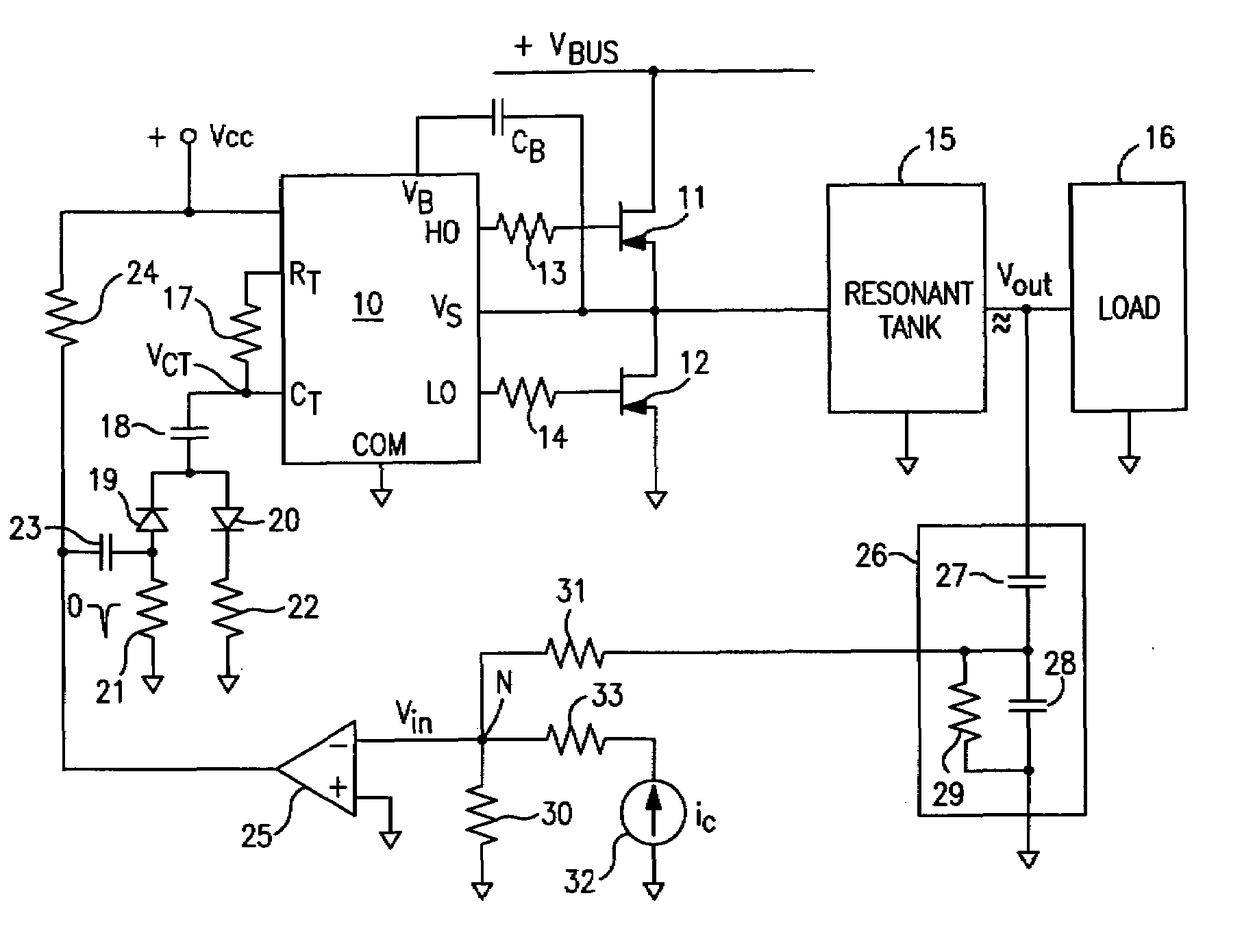
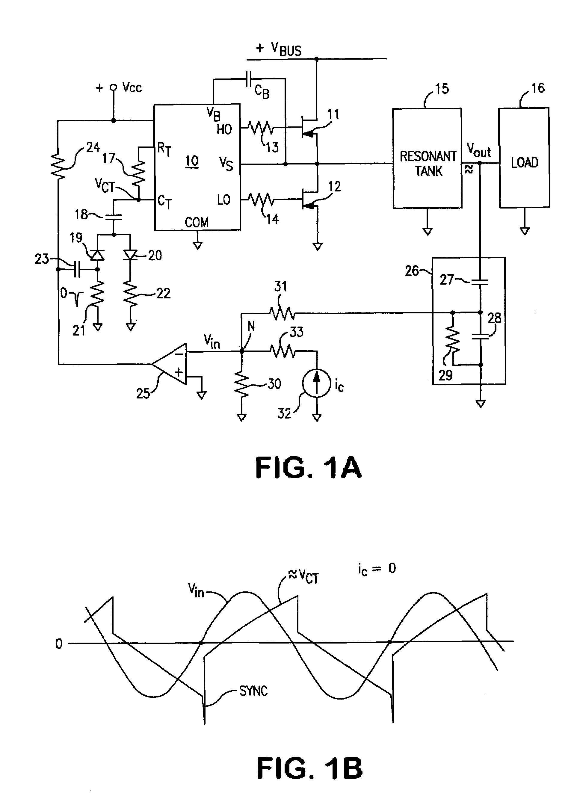
[0041]FIG. 1A is a ballast resonant inverter block-circuit diagram with a standard self-oscillating driver integrated circuit (IC) 10 that illustrates a synchronizing control arrangement of the present invention. HO and LO outputs of IC 10 drive a half bridge power stage that includes MOSFETs 11 and 12 and gate resistors 13 and 14. IC 10 is provided with a bootstrap capacitor CB connected to the pin VB of IC 10 coupled to a bootstrap diode (not shown). MOSFETs 11 and 12 are connected to high voltage (+V bus) DC for generating AC voltage across the input of a resonant tank 15. A load 16, such as a gas discharge lamp or a transformer with a rectifier with a filter, is coupled to resonant tank 15. The controller IC 10 has a built-in oscillator that is similar to the industry standard CMOS 555 timer. Initial oscillator frequency can be programmed with a timing circuit that includes external timing resistor 17 and timing capacitor 18 coupled to pins CT and RT of IC 10. In the circuit of ...


PUM


Abstract

A controller for a resonant inverter with a self-oscillating driver IC for powering AC loads, such as gas discharge lamps or regulated DC / DC converters, includes a timing circuit that generates control strobe pulses that are injected into the timing circuit. The timing circuit is coupled to an inverter resonant tank through a feed back circuit providing phase lock for the resonant inverter. The feed back circuit includes a passive phase shifting circuit for 360° closed loop phase shift. Phase controlled strobe pulses automatically adjust IC oscillator frequency for safe and stable inverter operation above resonant frequency. By injecting a small AC or DC control signal into the timing circuit, sync strobe pulse phase angle can be advanced or delayed and thus frequency and power of the phase lock system can be controlled.

Description

BACKGROUND OF THE INVENTION[0001]The present invention relates to resonant inverters for powering AC loads, preferably gas discharge lamps, and for dimming such lamps. The invention also relates to regulated DC / DC converter circuits.[0002]The following references are incorporated by reference: U.S. Pat. Nos. 5,245,253; 4,998,046; 6,246,183; 5,723,953; and 5,719,472; U.S. Patent Application US 2003 / 0147263 A1; IR Application Notes AN-995A “Electronic Ballast Using the Cost-Saving IR2155X Drivers”; IR Design Tip DT98-1, “Variable frequency Drive Using IR215X self oscillating IC's”; and “A Resonant Inverter for Electronic Ballast Application,” Melvin C. Cosby and R. M. Nelms, IEEE Transactions On Industrial Electronics, vol. 41, no. 4, August 1994.[0003]A gas discharge lamp typically utilizes electronic ballast for converting AC line voltage to high frequency current for powering the lamp. Conventional electronic ballasts include an AC to DC converter and a resonant inverter converting...

Claims


Application Information

Patent Timeline
Patent Type & Authority Patents(United States)
IPC IPC(8): H05B37/02H05B41/282
CPCH02M3/3382H05B41/2828Y10S315/07Y02B20/186Y02B70/1433Y02B20/185Y02B20/00Y02B70/10
Inventor ALEXANDROV, FELIX I.
Owner ABL IP HLDG
Why Eureka
Try Eureka