
Systems and methods for generating electrosurgical energy using a multistage power converter

a power converter and multi-stage technology, applied in the field of electrosurgical generators, can solve the problems of increasing heating, over-delivery of desired power, and slow control loop, so as to reduce thermal spread in tissue, reduce power deviation, and improve the dynamic response of the inverter

Active Publication Date: 2015-01-29
TYCO HEALTHCARE GRP LP
View PDF12 Cites 23 Cited by
  • Summary
  • Abstract
  • Description
  • Claims
  • Application Information

AI Technical Summary

Benefits of technology

The patent is about a new system and method for controlling the power in electrosurgical procedures. The system uses a two-stage power converter that adjusts the power based on the impedance of the tissue being treated. This reduces thermal spreading in the tissue and ensures a more controlled procedure. The system also includes a boost converter to lower ripples in the voltage and current, which improves the overall dynamic response of the inverter. Overall, this patent aims to improve the accuracy and safety of electrosurgical procedures.

Problems solved by technology

Although many other variables affect the total heating of the tissue, increased current density usually leads to increased heating.
This control loop, however, may be relatively slow compared to the switching frequency of the power stage.
Therefore, the power stage may under-deliver or over-deliver the desired power to the tissue until the control loop catches up with the power stage and the system reaches steady state.
For this and other reasons, current ES generators may fall short of providing the ideal output power characteristic.

Method used


Image

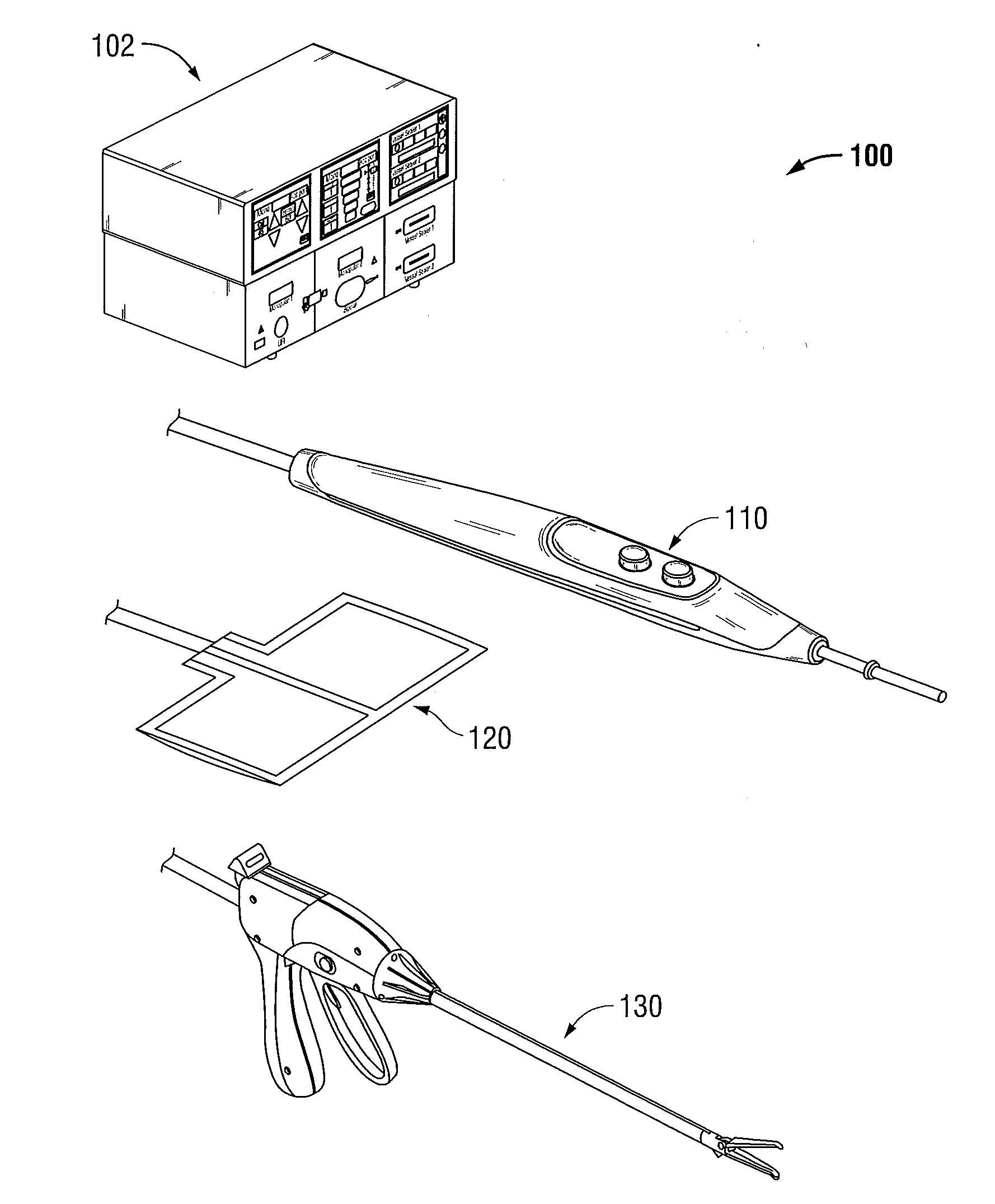
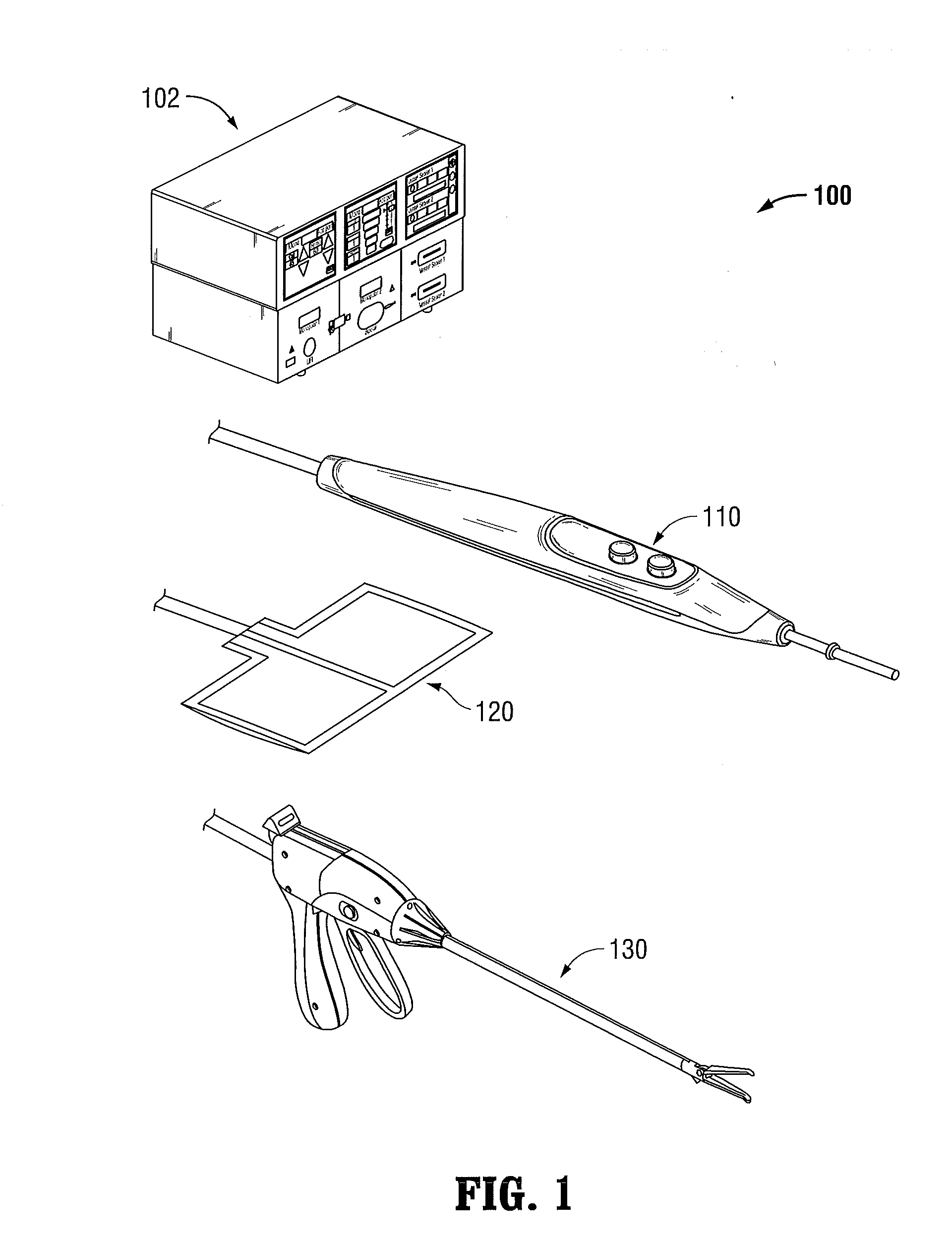
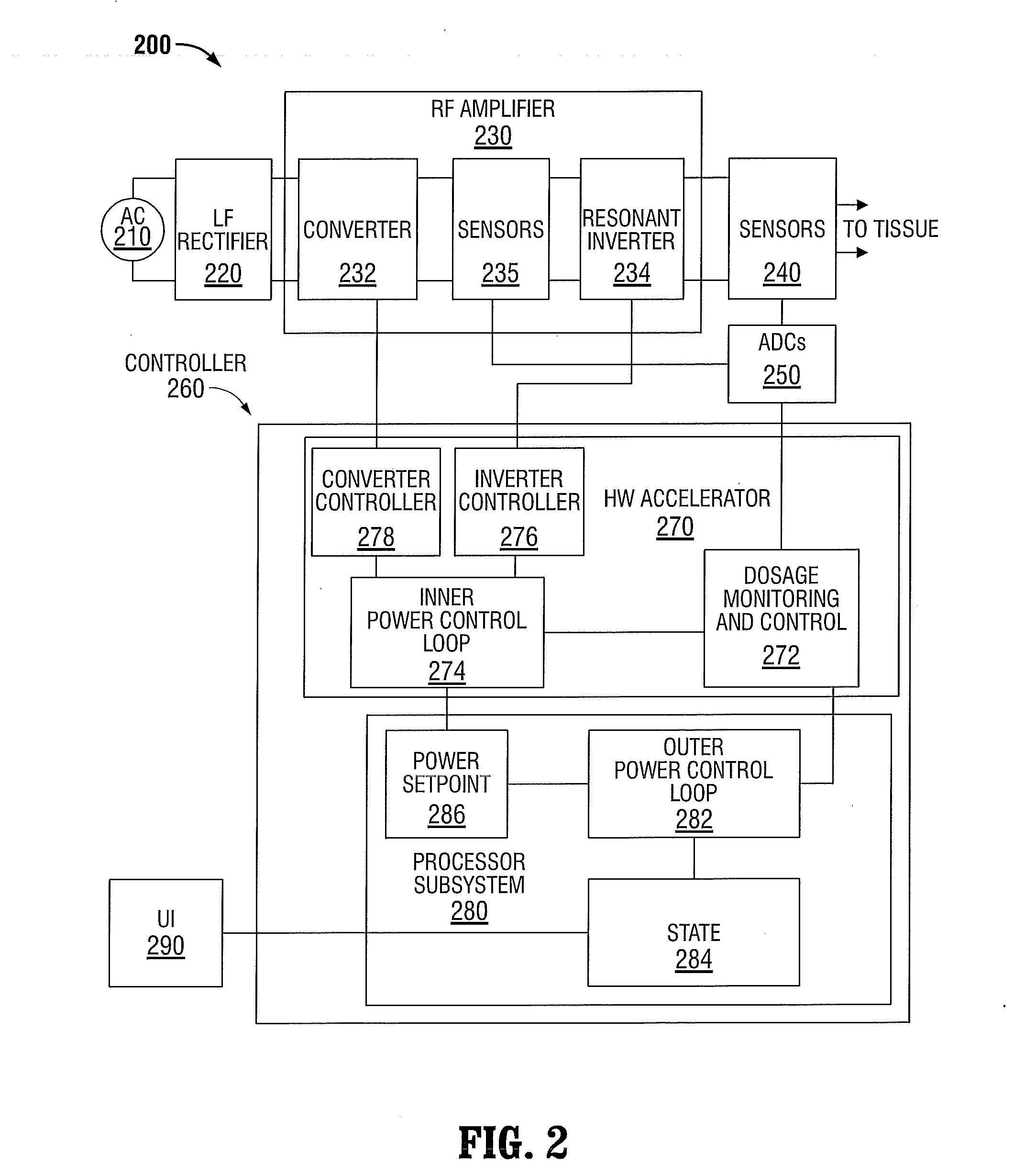
  • Systems and methods for generating electrosurgical energy using a multistage power converter
  • Systems and methods for generating electrosurgical energy using a multistage power converter
  • Systems and methods for generating electrosurgical energy using a multistage power converter

Examples


Embodiment Construction

[0032]To select an output characteristic among the constant current, constant voltage, and constant power output characteristics, typical methods sample output voltage and current waveforms, calculate power and / or impedance, feed these calculation results through a digital compensator, and then adjust the control variables of the output power converter's buck converter and resonant inverter. These processes are relatively slow compared to the switching frequency of the output power converter and, therefore, over-deliver or under-deliver the desired power until the control processes of the output power converter catch up and the system reaches a steady state. Thus, it is desirable to switch among the constant current, the constant power, and the constant voltage output characteristics quickly.

[0033]The systems and methods according to the present disclosure employ a multi-stage output power converter that can achieve a near ideal constant-current, constant-power, and constant-voltage...


PUM


Abstract

The electrosurgical systems and methods according to the present disclosure use a multi-stage power converter for generating electrosurgical energy. The electrosurgical systems include an electrosurgical generator having a power converter coupled to an electrical energy source and configured to generate electrosurgical energy. The power converter includes a boost converter configured to convert a first direct current from the electrical energy source to a second direct current, and a phase-shifted pulse width modulation (PS-PWM) resonant inverter configured to invert the second direct current to an alternating current. The electrosurgical generator also includes a plurality of sensors configured to sense a voltage and a current of the generated electrosurgical energy and a controller coupled to the power converter and the plurality of sensors. The controller includes a signal processor configured to determine tissue impedance based on the sensed voltage and current, and an output controller configured to select one of a plurality of output characteristics based on the determined tissue impedance, and to generate control signals to control the boost converter and the PS-PWM resonant inverter, according to the selected output characteristic.

Description

CROSS REFERENCE TO RELATED APPLICATION[0001]The present application claims the benefit of and priority to U.S. Provisional Application No. 61 / 858,037, filed on Jul. 24, 2013, the entire contents of which are incorporated herein by reference.BACKGROUND[0002]1. Technical Field[0003]The present disclosure relates to electrosurgery. More particularly, the present disclosure relates to electrosurgical generators and methods that use a multi-stage power converter for generating electrosurgical energy.[0004]2. Background of Related Art[0005]Electrosurgery involves the application of high-frequency electric current to cut or modify biological tissue during an electrosurgical procedure. Electrosurgery is performed using an electrosurgical generator, an active electrode, and a return electrode. The electrosurgical generator (also referred to as a power supply or waveform generator) generates an alternating current (AC), which is applied to a patient's tissue through the active electrode and i...

Claims


Application Information

Patent Timeline
Patent Type & Authority Applications(United States)
IPC IPC(8): A61B18/12
CPCA61B2018/128A61B18/1206A61B2018/00666A61B2018/0072A61B2018/00767A61B2018/00827A61B2018/00875A61B2018/00892A61B2018/1286H02M3/156H02M3/1584H02M7/06H02M1/007H02M7/4815Y02B70/10A61B2018/00702
Inventor JOHNSON, JOSHUA H.
Owner TYCO HEALTHCARE GRP LP
Learn More