Method of operating a resonant inverter using zero current switching and arbitrary frequency pulse width modulation

a resonant inverter and zero current technology, applied in the field of resonant inverters, can solve the problems of undesirable circulating current through the component, the use of frequency modulation to control the inverter output does not guarantee zero voltage switching, and the inability to operate as current sources. to achieve the effect of increasing the overall switching period

Inactive Publication Date: 2010-09-21
UNIVERSAL LIGHTING TECHNOLOGIES
View PDF14 Cites 20 Cited by
  • Summary
  • Abstract
  • Description
  • Claims
  • Application Information

AI Technical Summary

Benefits of technology

[0008]The method of the present invention includes turning off the bottom switch and turning on the top switch of a series-resonant half-bridge inverter when the current through the resonant inductor crosses the zero axis while the current is increasing. This insures zero voltage switching of the inverter switches. This operation also increases the overall switching period so that the actual inverter frequency is closer to the resonant frequency of the series-resonant circuit. By operating the inverter close to resonance, the open loop output impedance of the inverter is increased, providing a more stable operation of a load such as gas discharge lamp.
[0011]The first indicator signal is delivered to an input to the switching circuit. The switching circuit is operable to commutate the top and bottom inverter switches. Using the first indicator signal, the switching circuit causes the top inverter switch to turn on, and the bottom inverter switch to turn off, when the current in the resonant inductor crosses the zero-axis, while the inductor current is increasing. This insures zero-current switching of the inverter switches and increases the overall switching period so that the inverter operates closer to resonance.

Problems solved by technology

Unfortunately, prior art resonant inverters that operate as current sources suffer from several problems caused by deficiencies in the inverter switching methods.
For example, use of frequency modulation to control the inverter output does not guarantee zero voltage switching.
Moreover, with frequency modulation, the higher frequencies and higher lamp voltages associated with lamp dimming create undesirable circulating currents through the component and parasitic capacitances in the circuit.
Resonant inverters that use symmetric pulse width modulation (also known as dead time modulation) also have a high likelihood of non-zero voltage switching.

Method used


Image

  • Method of operating a resonant inverter using zero current switching and arbitrary frequency pulse width modulation
  • Method of operating a resonant inverter using zero current switching and arbitrary frequency pulse width modulation
  • Method of operating a resonant inverter using zero current switching and arbitrary frequency pulse width modulation

Examples


first embodiment

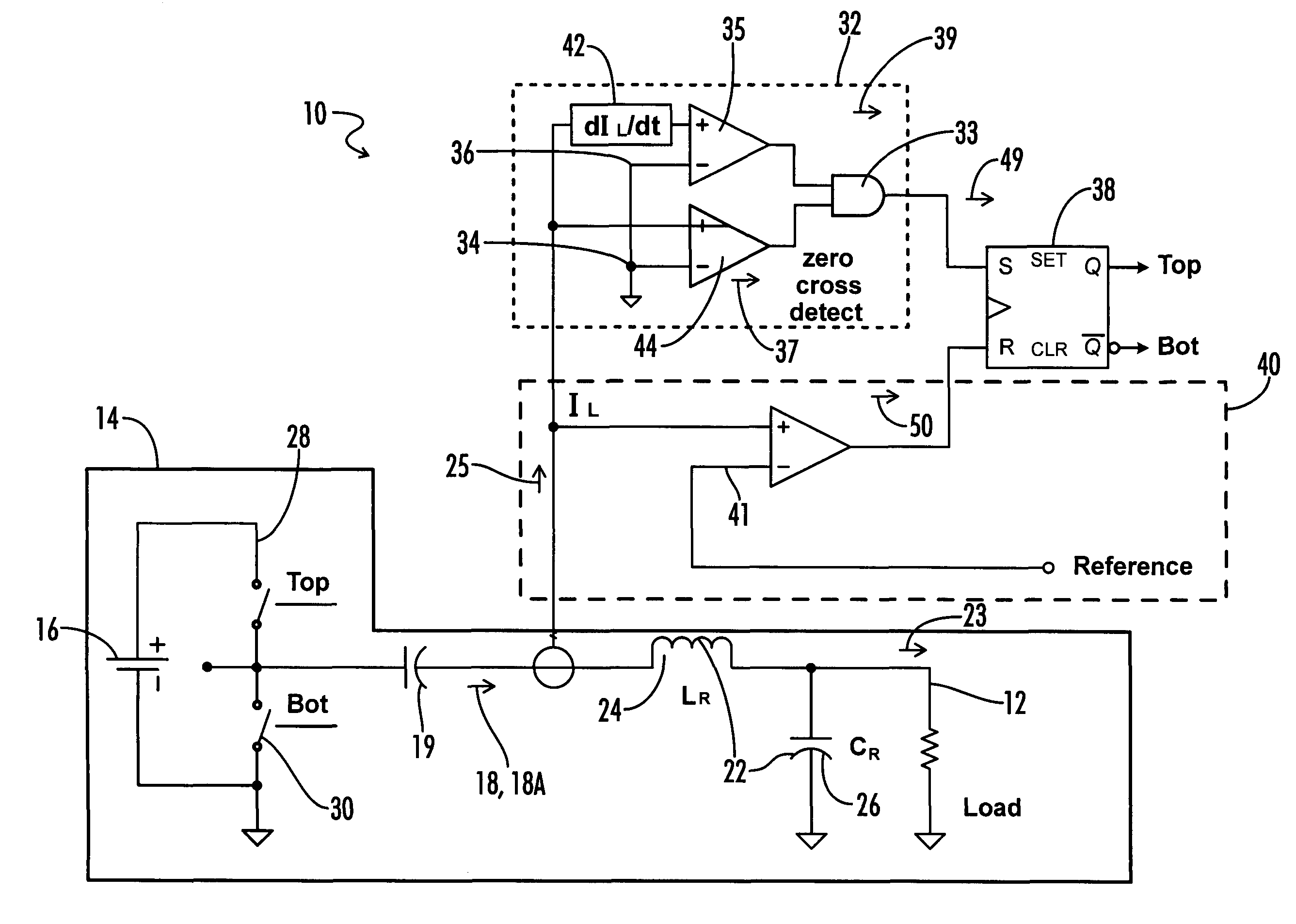
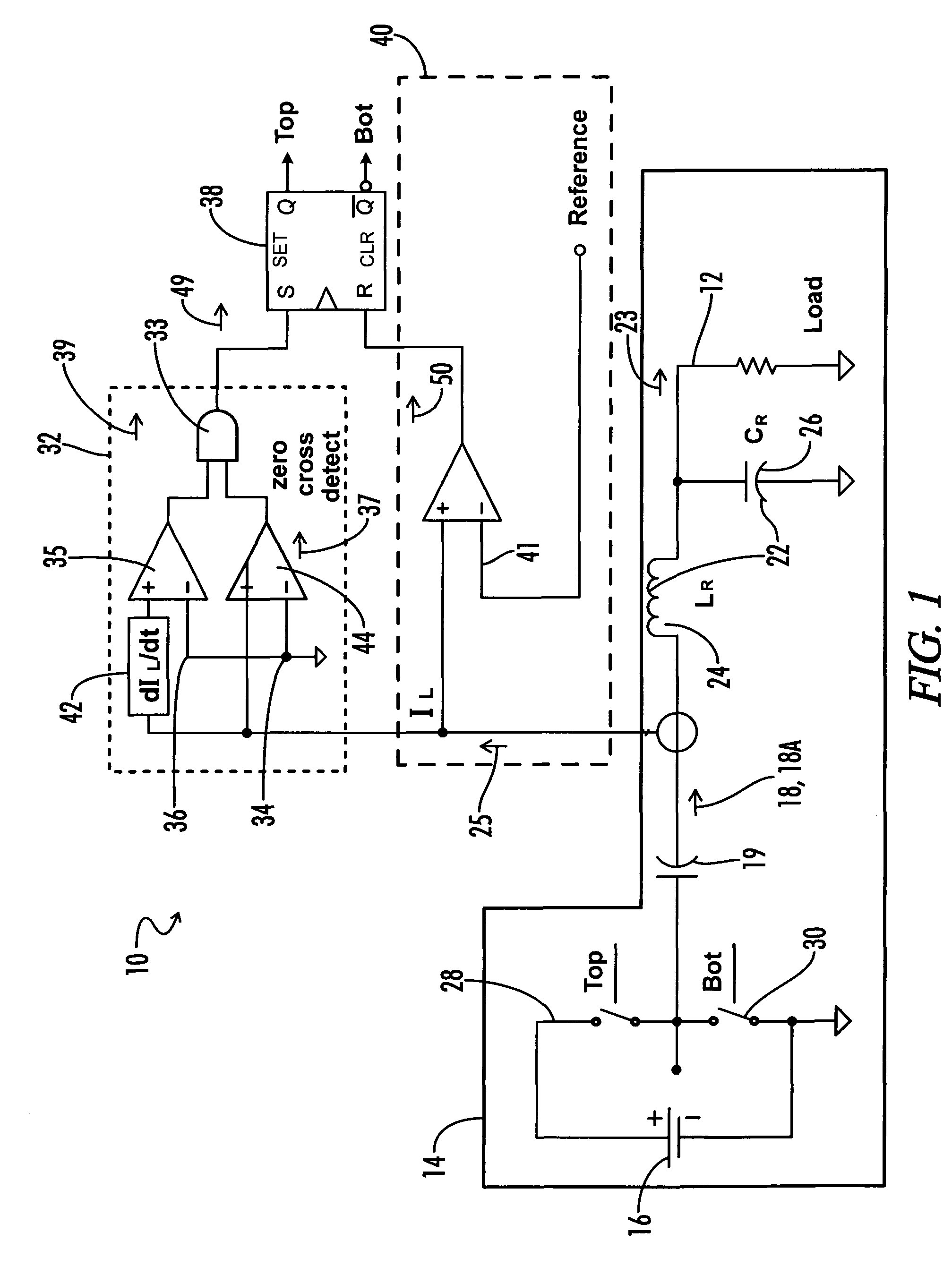
[0016]the inverter circuit 10 of the present invention is shown in FIG. 1. The inverter circuit 10 is particularly useful when the load 12 is a gas discharge lamp. The preferred embodiment stabilizes the operation of the lamp by maximizing the open loop output impedance of the inverter circuit.

[0017]The inverter circuit 10 includes a half-bridge inverter 14 coupled to a DC source 16 and a series-resonant circuit 22. The inverter 14 and series resonant circuit 22 conventionally operate to convert a DC voltage from DC source 16 to a high frequency, high voltage AC current that is supplied to a load 12, such as a gas discharge lamp. In this embodiment, the inverter 14 is a driven inverter in which commutation of the top and bottom inverter switches 28, 20 is controlled by an inverter drive circuit.

[0018]A DC blocking capacitor 19 may be placed between the inverter 14 and the resonant circuit 22. The inverter output 18 may have varying time, frequency, and envelope characteristics depen...

second embodiment

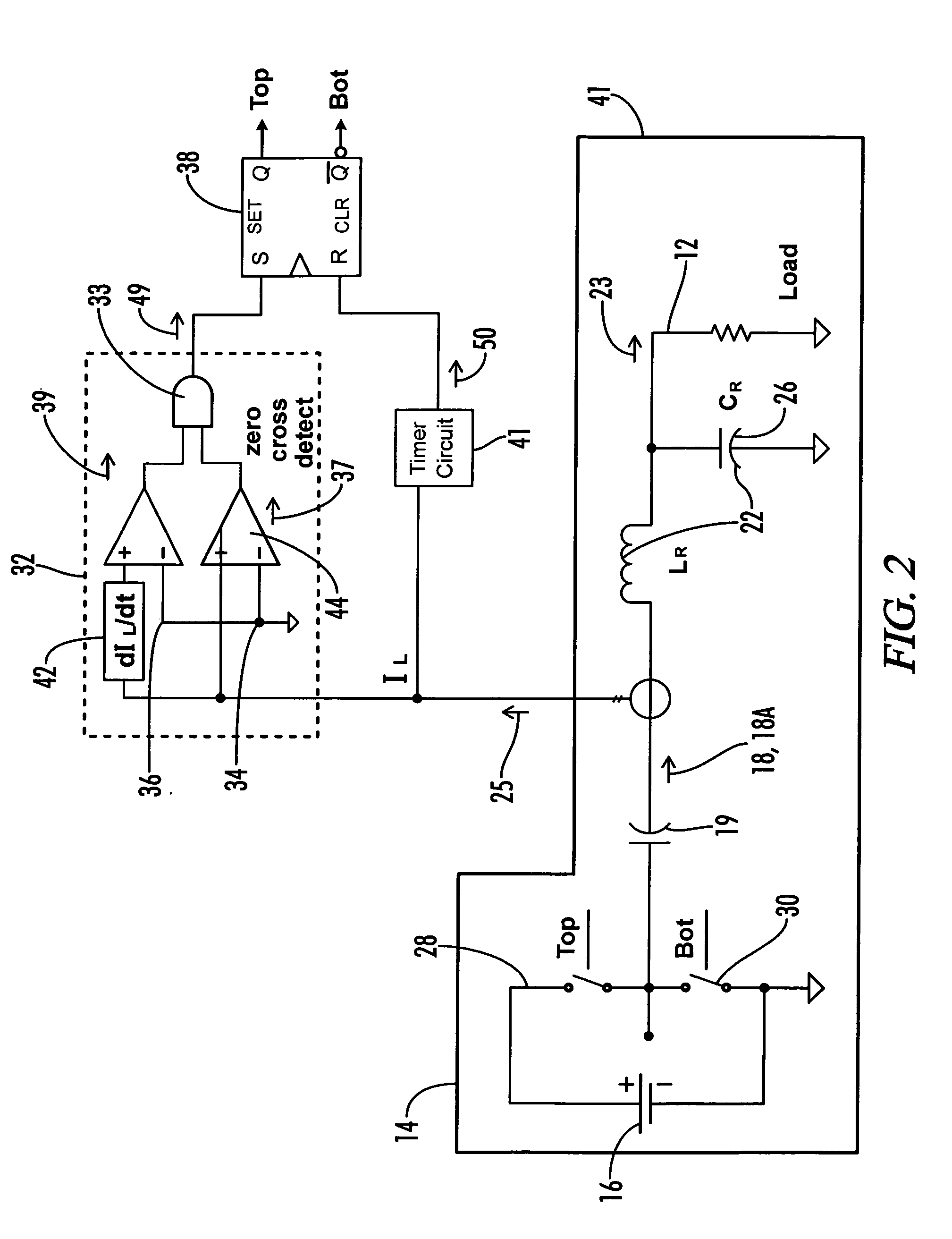
[0030]In the inverter circuit 10 shown in FIG. 2, the on-time of the top inverter switch 28 is controlled by a timer circuit 41. The timer circuit 41 is preferably activated when the top inverter switch 28 is turned on. Thereafter, the second indicator signal 50 is generated after a time delay, causing the top inverter switch 28 to turn off. Preferably, and as shown in FIG. 3B, the time delay is synchronized so that the top inverter switch 28 is turned off at or near a peak current value for the AC current signal 25. As described above, the zero-crossing detector circuit 32 insures commutation at or near zero current crossing when the load current is increasing.

[0031]A graphical illustration of the operation of the inverter circuit 20 is shown in FIGS. 3A-3B. Referring specifically to FIG. 3A, the graph depicts the output 31 from the normal output Q of switching circuit 38. When the output 31 is low, top inverter switch 28 is turned off. When the zero crossing detector circuit 32 de...


PUM


Abstract

A method of controlling a series-resonant, half-bridge inverter includes turning off the bottom switch and turning on the top switch the inverter when the current through the resonant inductor crosses the zero axis while the current is increasing, thereby insuring zero voltage switching of the inverter switches and increases the overall switching period so that the actual inverter frequency is closer to the resonant frequency of the series-resonant circuit. Using an on-time control circuit, the method further includes controlling the current delivered to the load (such as a gas discharge lamp) by varying the on-time of the top inverter switch.

Description

CROSS-REFERENCES TO RELATED APPLICATIONS[0001]None.BACKGROUND OF THE INVENTION[0002]The present invention relates generally to resonant inverters, such as those used in an electronic ballast to provide power to a gas discharge lamp. More particularly, the present invention pertains to methods of operating a resonant inverter-type electronic ballast to provide stable operation of, and to control power to, a gas discharge lamp.[0003]Electronic ballasts are commonly used to power gas discharge lamps, such as a fluorescent lamp. A typical electronic ballast will include a half-bridge resonant inverter driven by an inverter drive circuit. The inverter drive circuit controls the switching of the top and bottom inverter switches so that the inverter operates at or near the self-resonant frequency of the inverter. Using a driven resonant inverter allows for the lamp power to be controlled (for dimming and / or stable power regulation) by varying the inverter frequency and / or by varying the pu...

Claims


Application Information

Patent Timeline
Patent Type & Authority Patents(United States)
IPC IPC(8): H02M7/5387H02M3/24
CPCH02M7/523
Inventor DERNOVSEK, JOHN JAYMAYS, STEVE
Owner UNIVERSAL LIGHTING TECHNOLOGIES
Why Eureka
Try Eureka