Current-mode resonant inverter circuit

a resonant inverter and current mode technology, applied in the direction of dc-ac conversion without reversal, process and machine control, instruments, etc., can solve the problems of large leakage inductance of the step-up transformer in the inverter circuit, and the technical terms are not the same, so as to achieve easy illumination

Inactive Publication Date: 2006-08-31
CHEN HONG FEI +1
View PDF13 Cites 20 Cited by
  • Summary
  • Abstract
  • Description
  • Claims
  • Application Information

AI Technical Summary

Benefits of technology

[0081] Also, the inverter circuit is composed by a pair of a master (circuit and a sub circuit so that a discharge lamp requiring high voltage for lighting is lighted easily by double-side high voltage driving.

Problems solved by technology

Also, the leakage inductance of the step-up transformer in the inverter circuit is deemed disadvantageous in that it drops the output voltage on the secondary side of the transformer, and is desirable to be as small as possible.
The problem is how to describe the state in which a larger amount of flux leaks although the magnetic circuit structure is closed has been being discussed.
There is still a problem that these terms are not the technical terms which consider the above state.
Specifically, the transformer has a large leakage inductance.
These technical ideas, however, without having a viewpoint of the improvement power factor effect of the step-up transformer, are incorrect in that high efficiency is due to the reduction of heat generated in the switching transistor.
As a result, the power factor is not favorable in this case.
However, this is not the result of the use of the zero current switching method.
Consequently, the theory that the zero current switching method makes the inverter circuit higher conversion efficiency is wrong.
However, the cold cathode fluorescent lamps used for a liquid crystal display backlight for telivision are mostly long and their steady discharge voltages often exceed 1600V.
When trying to light the cold cathode fluorescent lamps, since a conventional current-mode resonant circuit is composed of a half-bridge circuit, it is difficult to drive the inverter circuit by direct commercial power so as to light the cold cathode fluorescent lamps.
However, the half-bridge circuit is less efficient in using the power supply voltage. FIG. 41 is an explanatory diagram illustrating the efficiency at which the half-bridge circuit uses the supply voltage, showing the voltage supplied to the transformer primary winding.
Furthermore, since the half-bridge configuration cannot respond to low power supply voltage, it is difficult to take full advantage of the power factor improvement effect disclosed in Japanese Patent No. 2733817 (U.S. Pat. No. 5,495,405).
In this case, however, there are sometimes fluctuations in parasitic (stray)capacitances caused by assembly methods for mass production, thereby deviating are caused with the secondary side resonance frequency circuit of the step-up transformer.
In such situations, constant driving at the optimum resonance frequency at which the power factor is improved is difficult.
If the resonance frequency of the secondary side circuit is shifted away from the drive frequency of the primary side circuit, the efficiency of the inverter circuit becomes extremely worse.
For such a reason, it is difficult to raise the Q value of the secondary side resonant circuit in the fixed-frequency separately-excited driving methods.
When trying to drive the secondary side resonant circuit with a low Q value by a conventional current-mode resonant circuit, continuous oscillation becomes difficult.
However, in a general step-up transformer for a cold cathode fluorescent lamp, the Q value of the secondary side resonant circuit is never set to high.
However, the measures involve problems that heat is generated easily in the step-up transformer.
However, also in this case, the half-bridge circuit, which is less efficient in using power voltage, cannot light a cold cathode fluorescent lamp directly due to its high discharge voltage.
Also, in the power control method by the conventional zero current switching method, power factor becomes worse when power is controlled for the following reason.
This means that the power factor is poor.
With the zero current switching method, idle current (reactive current) increases when power is controlled, thereby increasing copper loss in the step-up transformer primary winding, so that the conversion efficiency of the inverter circuit becomes worse.
When using the zero current switching method, power factor is poor particularly at a narrower (smaller) duty ratio as shown in FIG. 43.
In the zero current switching circuit, therefore, the operational frequency deviation is unavoidable when power is controlled.
Consequently, the power factor becomes extremely worse, and more heat is generated in the transformer primary winding due to increase in copper loss.
However, when the duty ratio is small, the long current delays in phase and consequently, the power factor becomes worse, and a larger current flowing through the transformer primary winding makes the inverter circuit conversion efficiency worse.
Particularly, as the duty ratio becomes smaller thereby delaying the current in phase closer to 90 deg., idle current increases rapidly thereby making the efficiency worse significantly.
In this case, significant heat is generated in the inverter circuit in practice.
Furthermore, there is also a problem that the operational frequency deviation of the inverter circuit is unavoidable when current is controlled by the zero current switching method.
On the contrary, the idea is damaging.

Method used


Image

  • Current-mode resonant inverter circuit
  • Current-mode resonant inverter circuit
  • Current-mode resonant inverter circuit

Examples


Embodiment Construction

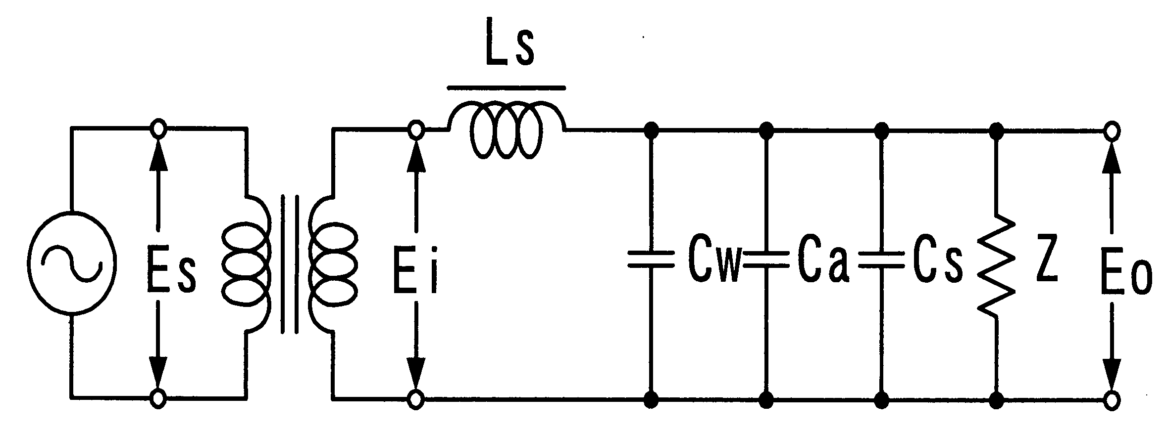
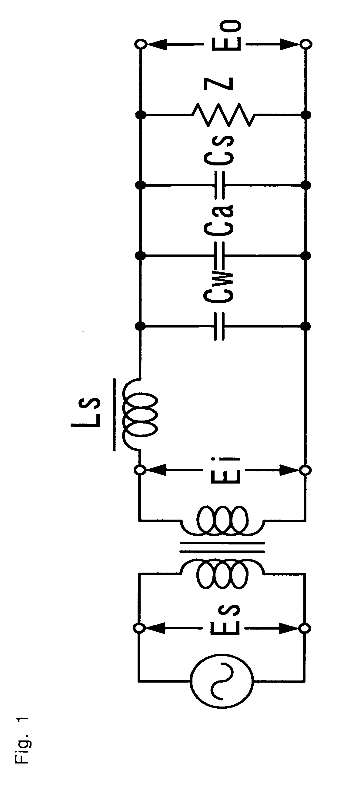
[0129] First, the resonant circuit in the present invention method the one shown in FIG. 1 or the step-up transformer in which the leakage inductance is replaced with a choking coil. In FIG. 1, capacitive components Cw, Ca and Cs in the secondary side circuit are combined so as to make the resonance capacitance and to compose the secondary side resonant circuit of the step-up transformer together with the leakage inductance Ls. In this case, the reference character Z denotes the impedance of a discharge lamp. In this case, the equation Ei=Es·k·N2 / N1 is true, in which k means coupling coefficient, and N1, N2 mean the number of turns of the transformer primary and secondary windings.

[0130] The oscillation frequency of the inverter circuit is determined by the resonance frequency of the secondary circuit. If the resonance frequency is set to fr: fr=12⁢ ⁢π⁢Ls·(CW+Ca+Cs)

[0131] The oscillation frequency of the current-mode resonant circuit in the present invention becomes the above freq...


PUM


Abstract

A high conversion efficiency inverter circuit by providing the current-mode resonant type efficient in using a power source. A current-mode resonant inverter circuit comprises a step-up transformer; the secondary winding side of the step-up transformer is composed of a resonant circuit between leakage inductance of the step-up transformer secondary winding and a capacitive component present in the secondary side circuit; one end of the step-up transformer primary winding is connected to the power source side; the other end of the primary winding is connected to a switched snubber circuit through the primary winding of a current transformer; the switched-snubber circuit comprises a pair of transistors different from each other in polarity; bases or gate of the pair of transistors, connected to each other, are connected to the secondary winding of the current transformer; either collector of the pair of transistors is connected to the primary winding of the current transformer; the other collector of the transistor is connected to the current transformer primary winding through a capacitor.

Description

[0001] This application claims priority to Japanese Patent Application No. 2005-005409 filed on Jan. 12, 2005. TECHNICAL FIELD [0002] The present invention relates to a dependent invention of the invention disclosed in Japanese Patent No. 2733817 (U.S. Pat. No. 5,495,405) by the inventor of the present invention or the use of the technical subject matters of that invention, and more particularly, to a current-mode resonant inverter circuit for a light source which is capacitive such as a hot cathode fluorescent lamp, a cold cathode fluorescent lamp (CCFL), an external electrode fluorescent lamp (EEFL), a neon lamp and any discharge lamps that has the similar characteristics. BACKGROUND OF THE INVENTION [0003] Recently, a surface light source has come to be used more widely, not only for displays for an advertisement and personal computer, but also for liquid crystal display television sets and the like. [0004] There is a demand of making an inverter circuit for driving these surface...

Claims


Application Information

Patent Timeline
Patent Type & Authority Applications(United States)
IPC IPC(8): H02M7/00H02M7/48H05B41/24
CPCH02M7/53838H05B41/2821Y02B70/1441Y02B70/10Y10S315/05H05B41/26
Inventor USHIJIMA, MASAKAZU
Owner CHEN HONG FEI
Why Eureka
Try Eureka