Series-Parallel Resonant Inverters

a series-parallel network and inverter technology, applied in the field of series-parallel resonant inverters, can solve the problem of complex calculation of the resonance frequency of the entire series-parallel network, and achieve the effect of high input voltage operation

Inactive Publication Date: 2011-06-16
HONEYWELL ASCA INC
View PDF5 Cites 18 Cited by
  • Summary
  • Abstract
  • Description
  • Claims
  • Application Information

AI Technical Summary

Benefits of technology

[0012]Induction heating for pulp and paper applications is characterized by a load, which typically does not change significantly. As such, a series-parallel resonant topology has significant advantages. These advantages include high input voltage operation, fault tolerance, non-resonant inverter current, low or zero-current switching, and multiple inverters from a common DC bus.

Problems solved by technology

The parallel resonant tank's resonant frequency is changed by the load, and thus the resonant frequency of the entire series-parallel network is complicated to calculate.

Method used


Image

  • Series-Parallel Resonant Inverters
  • Series-Parallel Resonant Inverters
  • Series-Parallel Resonant Inverters

Examples


Embodiment Construction

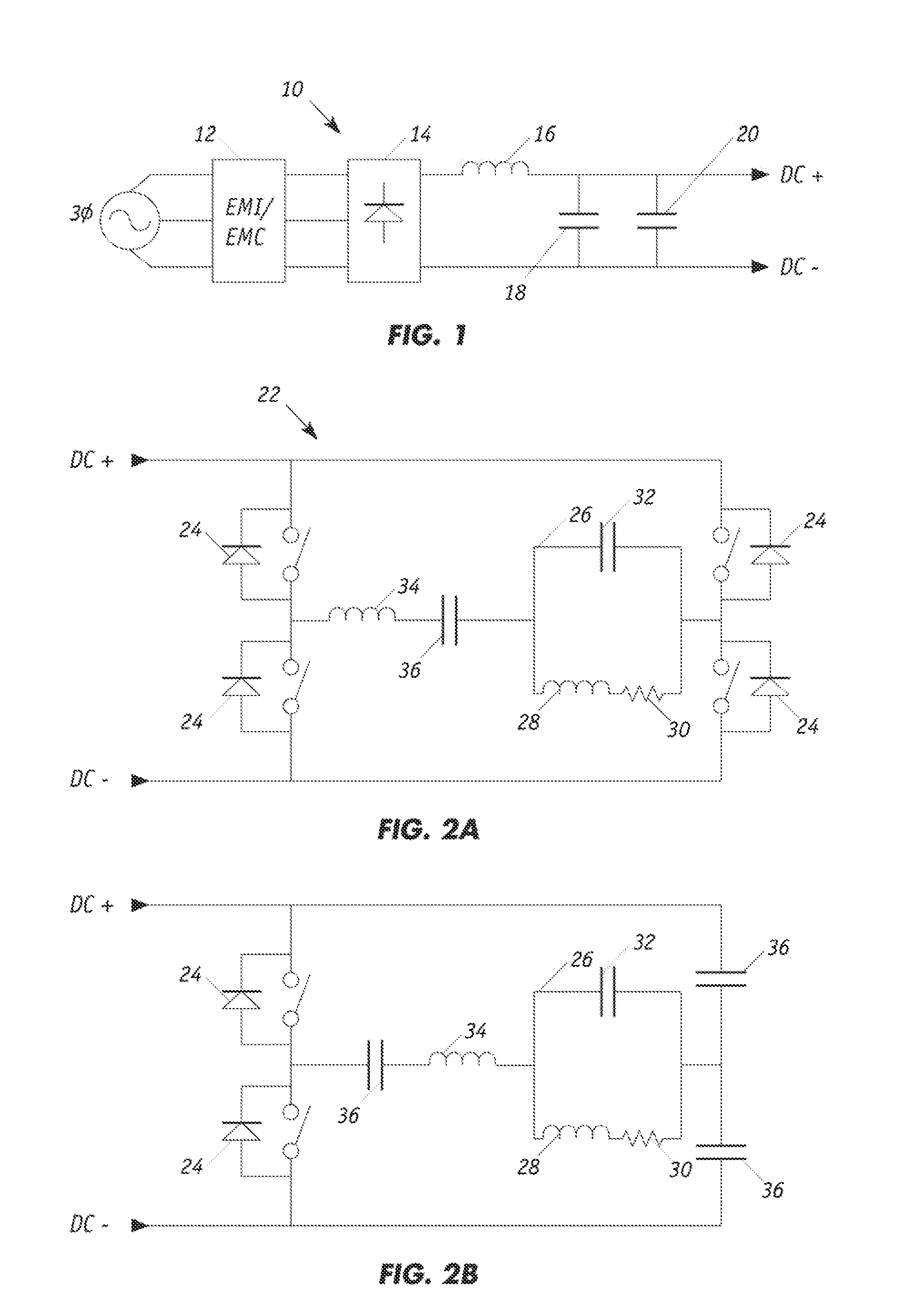
[0024]FIG. 1 illustrates a typical AC-DC converter 10 with rectification and filtering from which a stable DC source can be developed from a conventional 3-phase power source. An alternating voltage current undergoes electromagnetic interference and electromagnetic coupling filtering 12. The signal is next rectified by a diode rectifier 14. A final set of inductors 16 and capacitors 18, 20 filters out any remaining AC signal to generate an essentially pure DC output. This is possible as the impedance of a capacitor is Z(w)=1 / (jwC) and the impedance of an inductor is Z(w)=jwL. Here, Z(ω) is the impedance as a function of the natural frequency, C is the capacitance, L is the inductance, j is an imaginary value and ω is the natural frequency, a high value near infinity in the ideal case for an AC signal.

[0025]As such, the ideal embodiment yields infinite impedance for an inductor and zero impedance for a capacitor. Therefore, an AC signal cannot pass through an inductor but can pass th...


PUM


Abstract

A series-parallel resonant inverter inductively couples a switchable DC power source, which has a positive reference voltage node, a negative voltage reference node and a common reference node to a load. The load comprises a parallel resonator that is inductively coupled to the work piece and a series resonator. The series and parallel resonators each preferably has impedance, where the series circuit's impedance is greater than the impedance of the parallel circuit. The series resonator could include a high impedance inductor and a DC blocking capacitor in series with each other.

Description

RELATED APPLICATION DATA[0001]The present application is claims priority under 35 U.S.C. §119(e) to co-pending application for Series-Parallel Resonant Inverters, Application No. 61 / 285,946 filed Dec. 11, 2009, which is incorporated herein by reference.TECHNICAL FIELD OF THE INVENTION[0002]The present invention generally relates to resonant inverters and particularly to series-parallel resonant inverters particularly useful in industrial induction heating apparatus.BACKGROUND OF THE INVENTION[0003]In the operation of an exemplary induction heater, high frequency electromagnetic energy is applied to an electrically conductive work piece to be heated. This electromagnetic energy in turn induces a current flow in the conductive work piece.[0004]In an exemplary induction heater a switched DC power supply drives an inverter which converts the DC source voltage to a high frequency current. A work coil, which is an inductor within the inverter, transfers electromagnetic energy induced by t...

Claims


Application Information

Patent Timeline
Patent Type & Authority Applications(United States)
IPC IPC(8): H05B6/04G05F3/08
CPCH02M7/5387Y02B70/1441H05B6/04Y02B70/10
Inventor DOHMEIER, NICHOLASMCCORMICK, KEITH
Owner HONEYWELL ASCA INC
Why Eureka
Try Eureka