High Bandwidth Equalizer and Limiting Amplifier

a technology of equalizer and amplifier, applied in the field of equalization, amplification, offset compensation, can solve the problems of large area, power consumption of analog schemes, and inability to consider cost and circuit area,

Active Publication Date: 2014-02-06
AVAGO TECH INT SALES PTE LTD
View PDF8 Cites 16 Cited by
  • Summary
  • Abstract
  • Description
  • Claims
  • Application Information

AI Technical Summary

Problems solved by technology

This is undesirable for cost and circuit area considerations.
The analog schemes are power consuming and require large areas for implementation.

Method used


Image

  • High Bandwidth Equalizer and Limiting Amplifier
  • High Bandwidth Equalizer and Limiting Amplifier
  • High Bandwidth Equalizer and Limiting Amplifier

Examples


Embodiment Construction

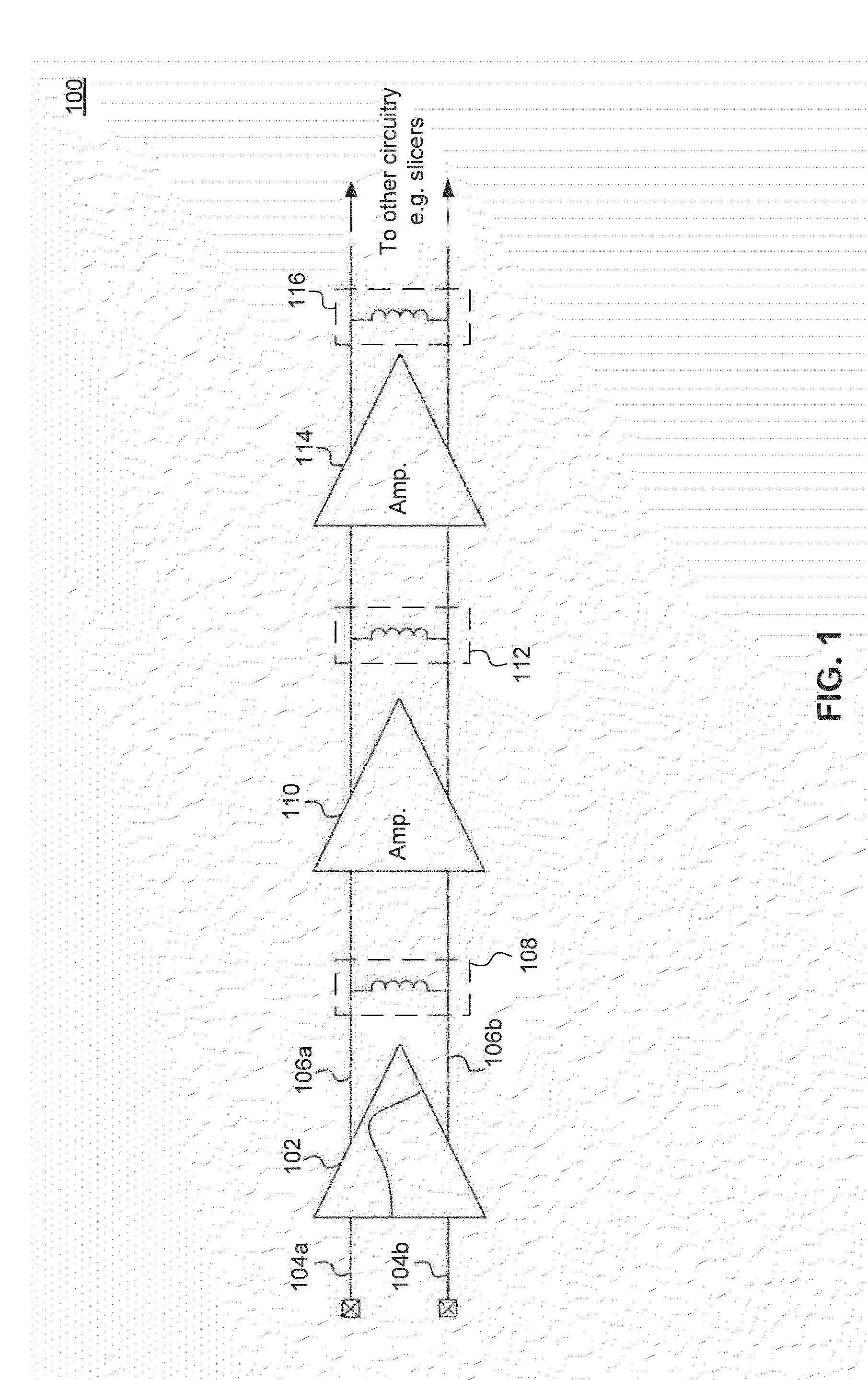
[0013]FIG. 1 illustrates a portion of a conventional receiver front-end circuit 100. As shown in FIG. 1, receiver front-end circuit 100 includes a peaking equalizer 102, followed by a plurality of amplifiers 110 and 114. Peaking equalizer 102 is configured to receive differential input data signals 104a and 104b, and to generate differential output data signals 106a and 106b. Differential output data signals 106a and 106b are coupled to amplifiers 110 and 114, before being provided to other circuitry, such as data slicers, for example. Amplifiers 110 and 114 may be limiting amplifiers, configured to attenuate or limit the portions of signals 106a and 106b that are above a certain level, in order to prevent saturation of subsequent stages.

[0014]For high data rate applications, differential input data signals 104a and 104b may have higher bandwidth than the respective bandwidths of equalizer 102 and amplifiers 110 and 114. Traditionally, therefore, large inductors, such as inductors 1...


PUM


Abstract

Embodiments of the present disclosure enable bandwidth extension of receiver front-end circuits without the use of inductors. As a result, significantly smaller and cheaper receiver implementations are made possible. In an embodiment, bandwidth extension is achieved by virtue of very small floating capacitors that are coupled around amplifier stages of the receiver front-end circuit. Each of the capacitors is configured to generate a negative capacitance for the preceding stage (e.g., equalizer or amplifier), thus extending the bandwidth of the preceding stage. A capacitively-degenerated cross-coupled transistor pair allows bandwidth extension for the final (e.g., amplifier) stage. Embodiments further enable DC offset compensation with the use of a digital feedback loop. The feedback loop can thus be turned on/off as needed, reducing power consumption.

Description

BACKGROUND[0001]1. Field of the Invention[0002]The present disclosure relates generally to equalization, amplification, and offset compensation.[0003]2. Background Art[0004]Conventional bandwidth extension of a receiver front-end circuit relies on large inductors placed after the various stages of the front-end circuit to extend their respective bandwidths. This is undesirable for cost and circuit area considerations. In addition, conventional receiver front-end circuits make use of analog feedback schemes to reduce device offsets. The analog schemes are power consuming and require large areas for implementation.BRIEF DESCRIPTION OF THE DRAWINGS / FIGURES[0005]The accompanying drawings, which are incorporated herein and form a part of the specification, illustrate the present disclosure and, together with the description, further serve to explain the principles of the disclosure and to enable a person skilled in the pertinent art to make and use the disclosure.[0006]FIG. 1 illustrates...

Claims


Application Information

Patent Timeline
Patent Type & Authority Applications(United States)
IPC IPC(8): H04L27/01
CPCH04B3/04H04B3/14H04L25/03878H04L25/063H04L27/0002
Inventor ALI, TAMERNAZEMI, ALIKOCAMAN, NAMIK
Owner AVAGO TECH INT SALES PTE LTD
Why Eureka
Try Eureka