Suction Chuck and Workpiece Transfer Apparatus Including the Same

Inactive Publication Date: 2014-02-06
MURATA MASCH LTD
View PDF5 Cites 22 Cited by
  • Summary
  • Abstract
  • Description
  • Claims
  • Application Information

AI Technical Summary

Benefits of technology

[0012]The present invention has been made in view of the circumstances described above, and a primary object of the present invention is to provide a suction chuck

Problems solved by technology

In a case where the Bernoulli chuck has a size smaller than a workpiece, the thin plate workpiece may vibrate and contact an outer periphery (edge) of the Bernoulli chuck at

Method used


Image

  • Suction Chuck and Workpiece Transfer Apparatus Including the Same
  • Suction Chuck and Workpiece Transfer Apparatus Including the Same
  • Suction Chuck and Workpiece Transfer Apparatus Including the Same

Examples


Embodiment Construction

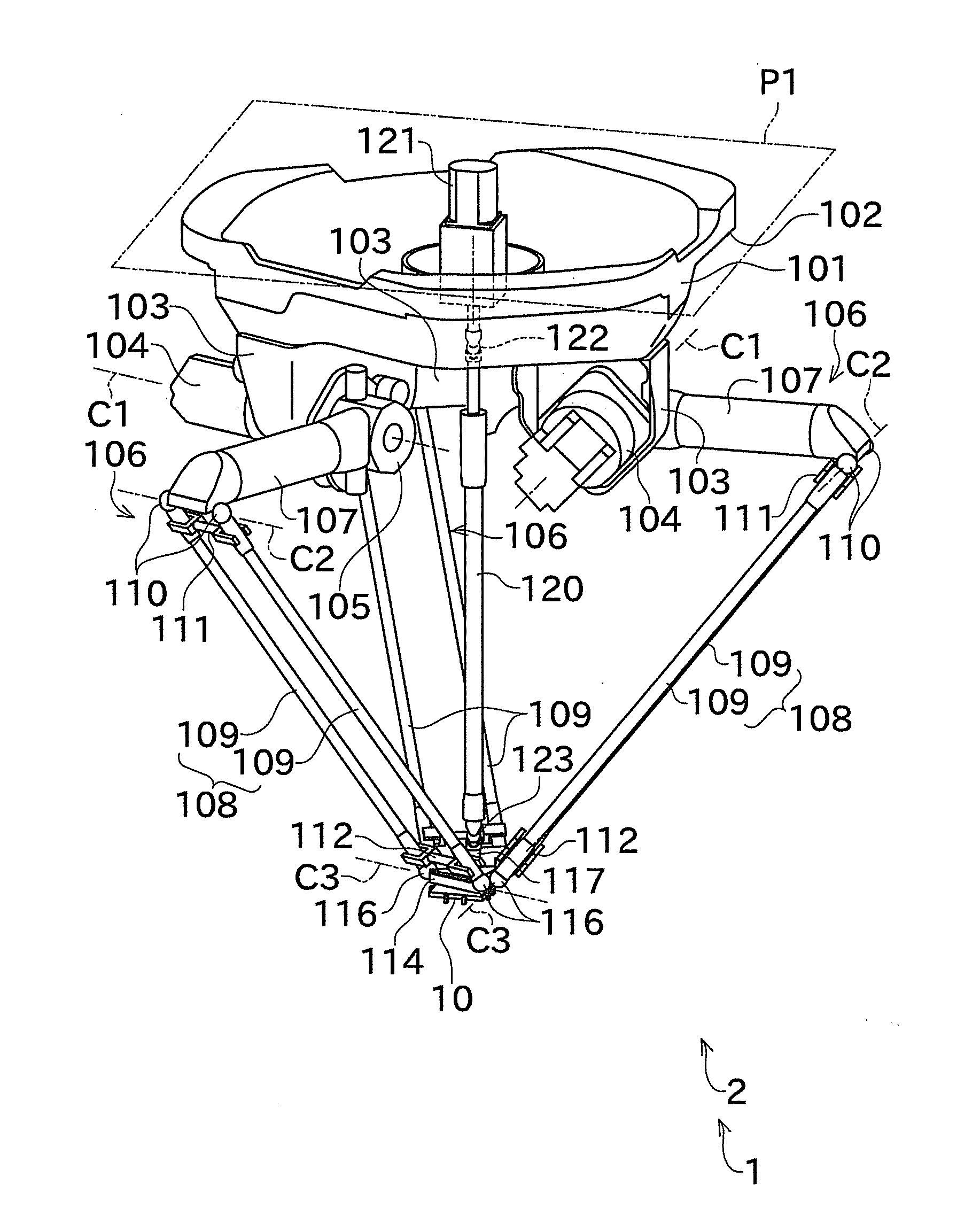
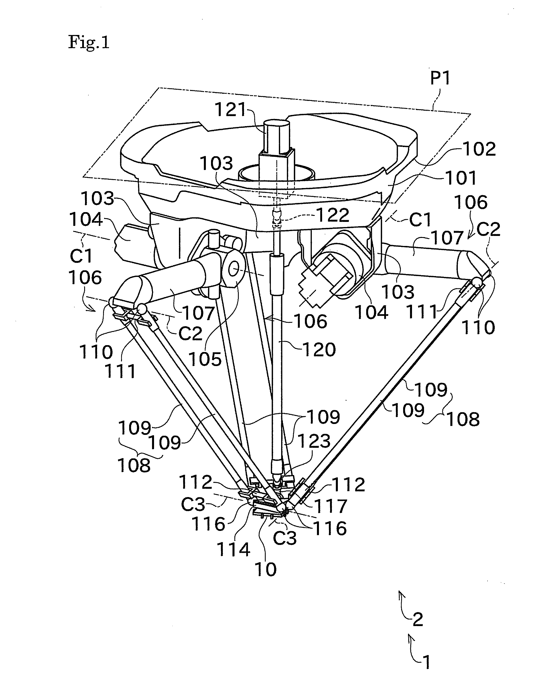
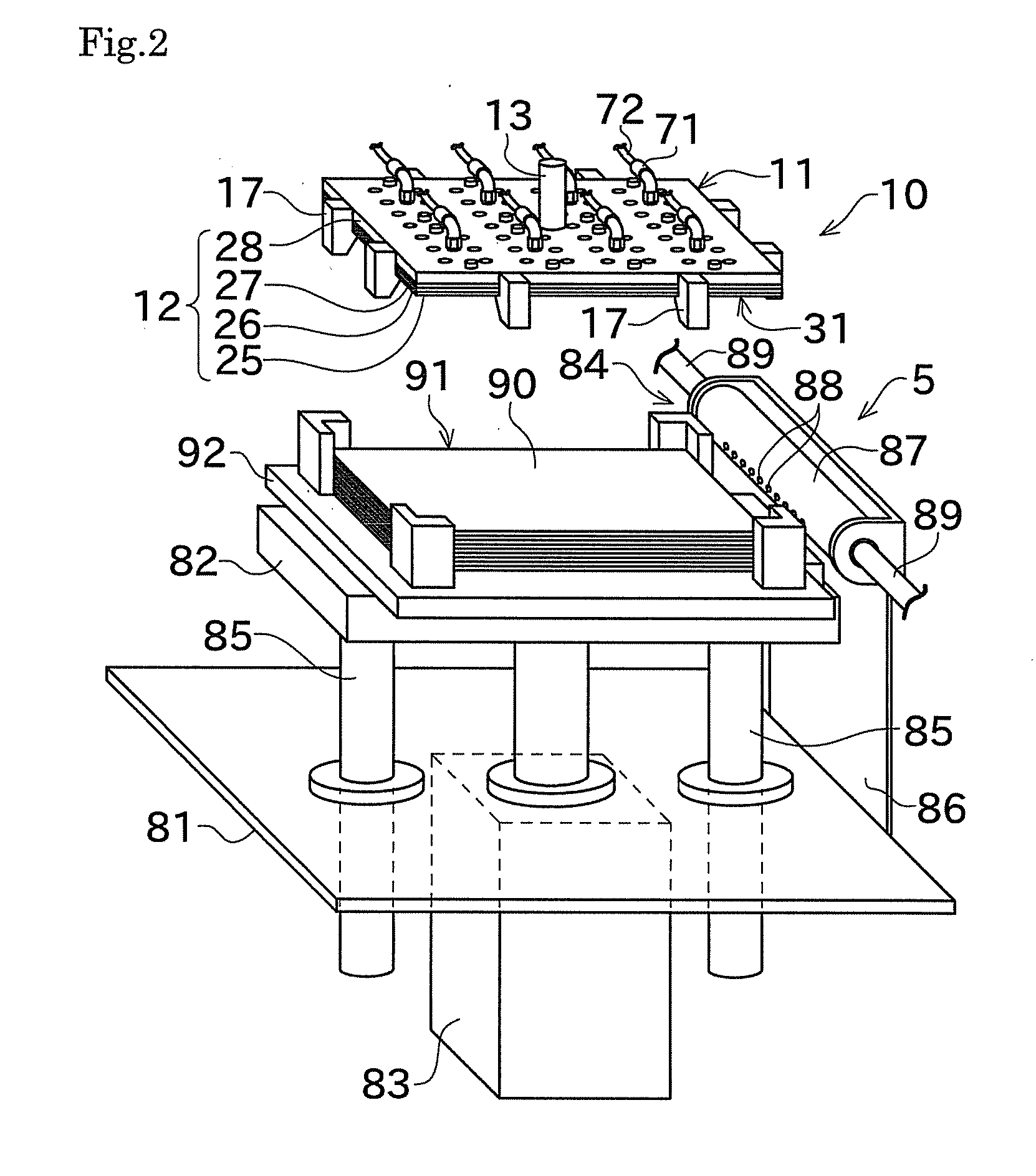
[0076]Next, an embodiment of the present invention will be described with reference to the drawings. FIG. 1 is a perspective view showing a transfer robot 1 serving as a transfer apparatus according to an embodiment of the present invention. FIG. 2 is a perspective view showing a workpiece feeder 5 included in the transfer robot 1.

[0077]As shown in FIG. 1, the transfer robot (transfer apparatus) 1 of this embodiment includes a parallel mechanism 2 having a suction chuck (Bernoulli chuck) 10 mounted thereto. The parallel mechanism 2 mainly includes a base member 101, support members 103, electric motors 104, arm support members 105, arm main bodies 106, and an end plate 114. As shown in FIG. 2, the transfer robot 1 includes the workpiece feeder 5 that is configured to feed a workpiece 90 having a flat plate shape, which is an object of transfer, to the parallel mechanism 2. FIG. 2 shows the suction chuck 10 in a state of being removed from the parallel mechanism 2, for facilitating t...


PUM


Abstract

Provided is a suction chuck that is lightweight and that sucks and releases a thin plate workpiece in such a manner that the thin plate workpiece is not in contact with an edge of the chuck. A suction chuck according to an embodiment of the present invention includes a main body having a flat plate shape, and an opposing surface. Compressed air passages are formed within the main body. The opposing surface is a surface of the main body at the side facing the workpiece. The opposing surface has a plurality of recesses formed therein. The plurality of recesses serve as a sucking element for generating a negative pressure by ejecting the compressed air. The opposing surface is formed with a shape similar to the shape of the workpiece (or with a shape that corresponds to the shape of the workpiece being offset outward) such that the shape of the opposing surface is able to completely cover the shape of the workpiece when seen along a direction perpendicular to the opposing surface. The recesses are arranged such that all of the recesses are coverable by the shape of the workpiece when seen along the direction perpendicular to the opposing surface.

Description

TECHNICAL FIELD[0001]The present invention relates mainly to a suction chuck for sucking a workpiece of thin flat-plate shape and holding the workpiece in a non-contact state.BACKGROUND ART[0002]For transfer of a workpiece (thin plate workpiece) in the shape of a thin flat plate such as a solar cell wafer, a fuel battery cell, or an electrode or a separator of a secondary battery, a transfer apparatus that adopts a Bernoulli chuck using the Bernoulli effect as an end effector has been conventionally proposed (for example, see Patent Document 1).[0003]The present applicant proposes, as a transfer mechanism of the transfer apparatus, a parallel mechanism robot disclosed in Patent Document 2, and also proposes, as a suction chuck, a Bernoulli chuck disclosed in Patent Document 3.[0004]In the Bernoulli chuck, because of its structure, occurrence of vertical vibrations of a thin plate workpiece being sucked is inevitable. In a case where the Bernoulli chuck has a size smaller than a work...

Claims


Application Information

Patent Timeline
IPC IPC(8): B25J15/06
CPCB25J15/0616B25J15/0675H01L21/6838Y10T279/11H01L21/67742
Inventor TAKASHIMA, HIROKINAKANISHI, HIDEAKI
Owner MURATA MASCH LTD
Why Eureka
Try Eureka