

Encapsulated Preformed Shapes
- Summary
- Abstract
- Description
- Claims
- Application Information
AI Technical Summary
Benefits of technology
Problems solved by technology
Method used
Image

Examples
example composite
Wear Parts
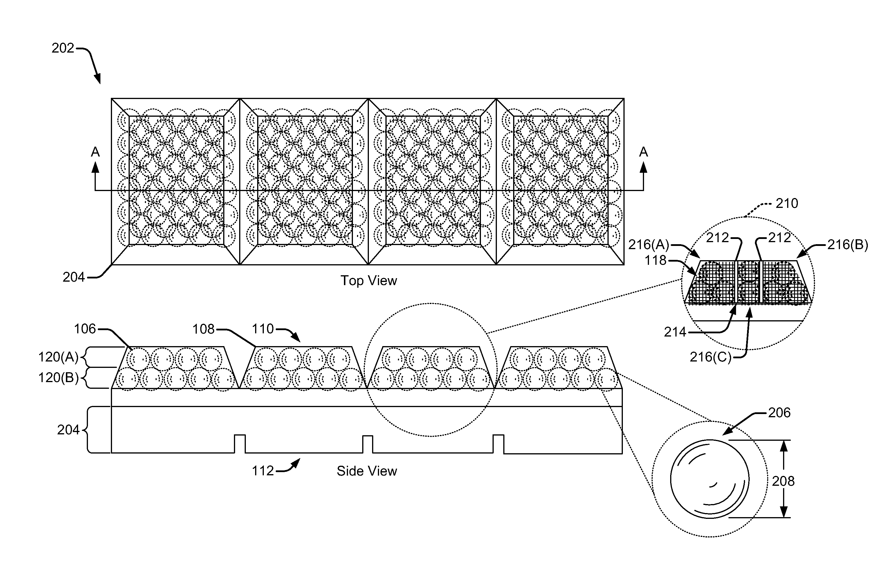
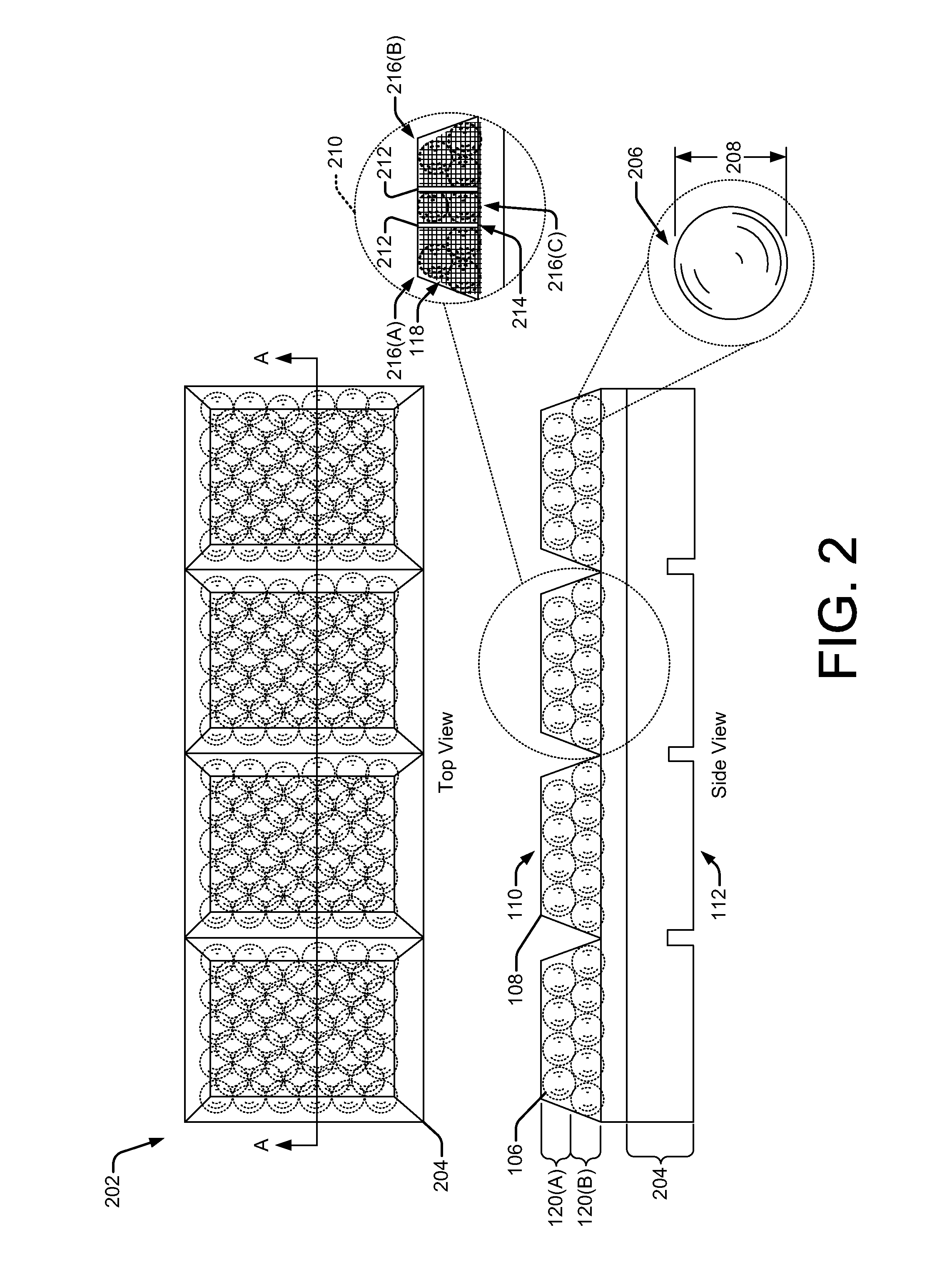
[0041]This section describes exemplary composite wear parts including a plurality of preformed ceramic shapes embedded in a base metal.
[0042]In some implementations, the plurality of preformed ceramic shapes may include a plurality of elements having a uniform, preformed geometry. The preformed geometry being such that the plurality of preformed ceramic shapes are configured to pack together in a uniform way to provide for being positioned at a location in the composite wear part exposed to an abrasion. These and numerous other composite wear parts can be formed according to the techniques described in this section.
[0043]Metal / ceramic composite materials are well suited to abrasion-resistant applications due to the characteristics of the materials. For example, metals typically provide a relatively high strength-to-weight ratio and a high toughness, while ceramics have a relatively high hardness.
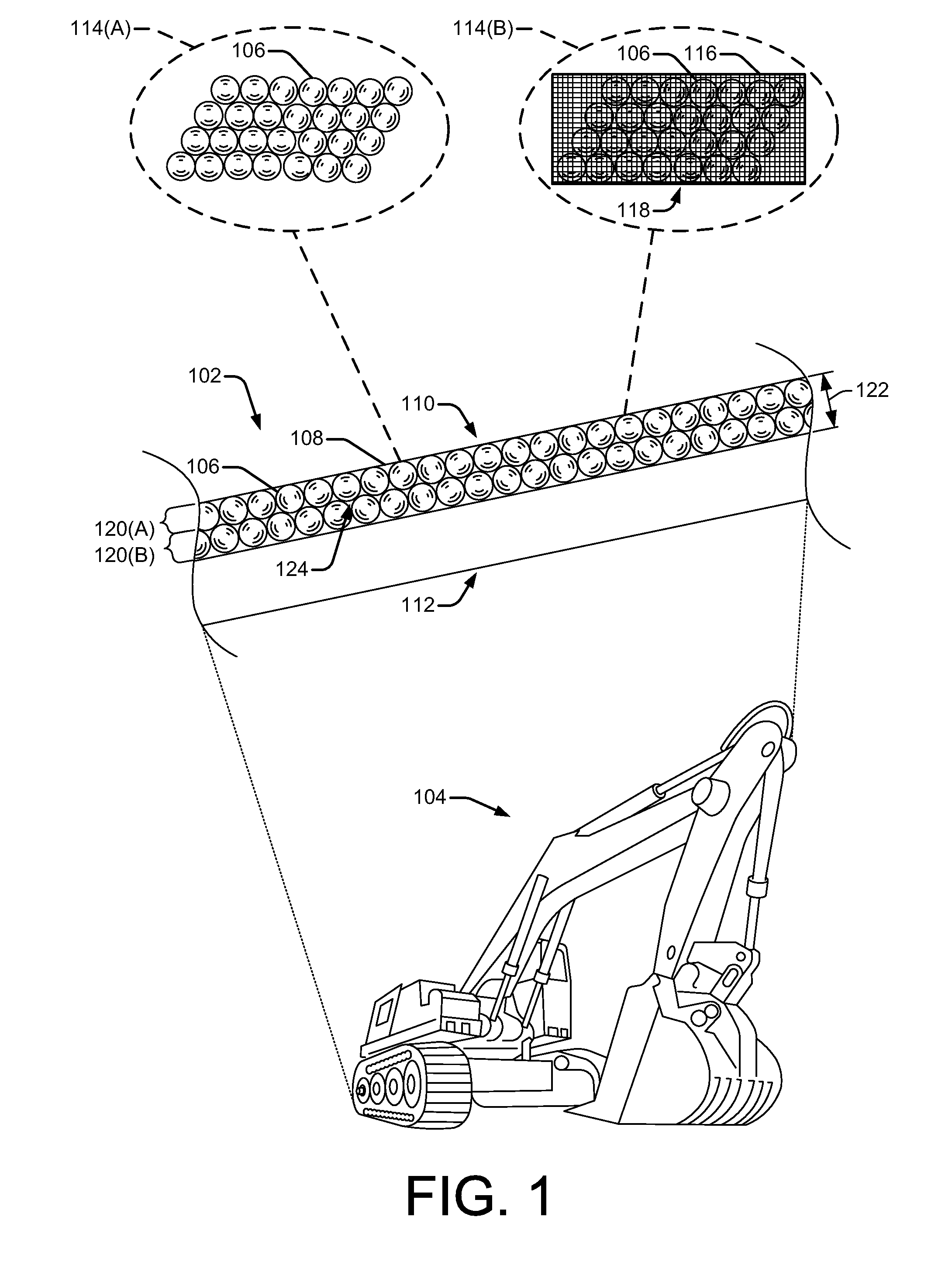
[0044]FIG. 1 is a side view diagram of a composite wear part 102 used, for exa...
PUM
| Property | Measurement | Unit |
|---|---|---|
| Diameter | aaaaa | aaaaa |
| Diameter | aaaaa | aaaaa |
| Electrical resistance | aaaaa | aaaaa |
Abstract
Description
Claims
Application Information